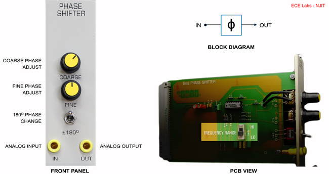
PHASE SHIFTER
The PHASE SHIFTER introduces a phase shift between its input and output. This phase shift is adjustable by the user. The frequency range of operation can be selected by PCB mounted switch.
USE
This variable PHASE SHIFTER is capable of varying the magnitude of the phase shift through 360 degrees in two steps. The 180 degree switch selects the step or region of interest; the COARSE and FINE controls are used to then obtain the required phase shift, Φ.
If the input is COS(μt), then the output is COS(μt- Φ), where Φ lies between 0 and 180 degrees. Although the PHASE SHIFTER will operate from a few hertz up to 1MHz it has been optimized to operate in the neighborhood of two frequencies: around 100kHz in the HI range and around 2kHz in the LO range. A PCB mounted switch is used to select the frequency range.
The open circuit gain through the PHASE SHIFTER is essentially unity for all phases, but note that the amount of phase shift, Φ, is a function of frequency. This is NOT a wideband phase changer: thus all the frequency components of a complex signal's spectra are not shifted by the same phase.
BASIC SPECIFICATIONS
Bandwidth < 1MHz
Frequency Range: HI approx 100kHz *
LO approx 2kHz *
* For 0 to 360 degree range of phase shift. The phase shift range increases (i.e. resolution decreases) as the input frequency increases.
Coarse approx 180 degrees shift.
Fine approx 20 degrees shift.
PARAMETERS TO NOTE
Variation of phase change with frequency change.

