LAB 7: CDMA AT CARRIER FREQUENCIES
Extra Modules:
ADDER, PHASE SHIFTER, QUADRATURE UTILITIES, SEQUENCE GENERATOR, QUADRATURE UTILITIES, SEQUENCE GENERATOR, CDMA DECODER, DIGITAL UTILITIES, ERROR COUNTING UTILITIES, MULTIPLE SEQUENCES SOURCE, NOISE GENERATOR, WIDEBAND TRUE RMS METER.
optional: 100 kHz CHANNEL FILTERS.
Pre-lab
Baseband spread spectrum signal. In this sheet a two-channel bandpass CDMA system is modelled, with the messages spread around a 100 kHz carrier. This more closely resembles a cellular radio CDMA system.
The spectrum of the transmitted signals will extend either side of the carrier frequency ωc, which in TIMS is typically 100 kHz. In order to achieve a reasonable processing gain the bandwidth B1 of the message sequence should be considerably less than B2, the bandwidth of the PN spreading sequence. But the bandwidth of the spread signal should not extend to DC, so this requires that B2 < ωc.
Generation
One method of generation of a single DSSS generator at carrier frequencies is illustrated in the block diagram of Figure 1. Other methods are possible.
Figure 1: 1 of 'n' DSSS sources.
The transmission medium (not shown) can be simply an ADDER. A bandlimited medium is not essential, but a bandpass filter1, plus perhaps an optical fibre2 , or a pair of antennas3, could be included. The transmitted signal is spread around the carrier frequency. Two such DSSS, combined in the channel (not at baseband), together with noise, constitute a two channel CDMA system.
As resources permit, further channels can be added.
1 match the signal bandwidth to that of the bandpass filter in the 100 kHz CHANNEL FILTERS module.
2 using FIBRE OPTIC TX and FIBRE OPTIC RX modules.
3 using 100kHz TX ANTENNA and 100kHz RX ANTENNA UTILITIES modules.
Reception
A demodulator and decoder, for one channel at a time, is illustrated in Figure 2. This first translates the bandpass signal back to baseband, where it is de-spread. A comparator is used to 'clean up' the received signal. Bit error rate (BER) instrumentation is included.
Figure 2: Receiver - Decoder - BER measurement
Experiment
A two-channel transmitter is illustrated in Figure 3. The two channels are combined at 100 kHz in the ADDER of a QUADRATURE UTILITIES module. A second ADDER is used to introduce the noise
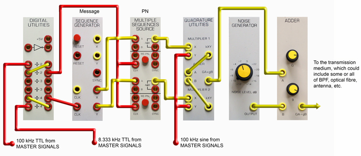
Figure 3: 2-channel 100 kHz system model - transmitter.
In the model a carrier frequency of 100 kHz is shown. To satisfy the bandwidth requirements choose division ratios so that the message clock could be 512 Hz, and the PN spreading clock 8.333 kHz

Figure 4: system model - receiver, decoder, and error counting
A decoder for a single channel is shown modelled in Figure 4. Channels can be changed by PN sequence selection in the CDMA DECODER module.
See your Lab Manager for measurement suggestions; at the very least investigate the BER change when the second channel is added or removed.
Instructions
- Assemble the transmitter of Figure 3, wiring only one of the two channels at this time. Check that the Spectra are what you expect at locations 1, 2, 3, and 4. Make certain that you set the multiple sequence source switches to give you different patterns on the two channels. Remember which pattern you are using for each channel. Measure the distance from the peak of the spectrum to the first null or the distance between the innermost nulls and compare with the theory from the "Spectrum of CDMA Signals" document. Make certain the signal out of the transmitter is what you expect.
- Assemble the receiver of figure figure 4. Check to make certain that the clock from the CDMA decoder is putting out a signal. You may need to adjust the knob between the clock in and the clock out of the CDMA decoder to get a good clock signal. Check that the received pattern (CDMA decoder output) matches the initial message sequence. If you have a difficult time recovering the initial sequence you may want to try removing the carrier multiplication in both transmitter and receiver and seeing if you can get the baseband to work.
- To make a BER measurement, the two codes being compared have to be in sync. See if you can figure out how to make this happen. If you need help during lab, ask the instructor.
- Measure the BER of your system with no noise and only one channel wired up. Increase the counting period until you either get errors or you've reached the maximum counting period.
- Now wire up the second channel using the Quadrature Utilities Module to add the two channels together after they are multiplied by the 100kHz carrier signal. Repeat the BER counting to see if there is an increase in errors due to the presence of the second channel. The second channel is spread out like noise in the system. You can now remove the second channel and see if you can obtain approximately the same error rate with noise that you observed by adding in the second channel.
- If you have time left, you can explore any of these:
- Jamming with a single sinusoid rather than broad band noise. Is it easier to jam at the bit rate or the chip rate or the carrier?
- A careful BER vs S/N plot
- Decode the other channel and see if it behaves similar to the first.
- Add a third channel?