M-LEVEL ENCODER
(m-QAM & m - PSK CONSTELLATION GENERATOR)
MULTI-LEVEL ENCODER SECTION GUIDE
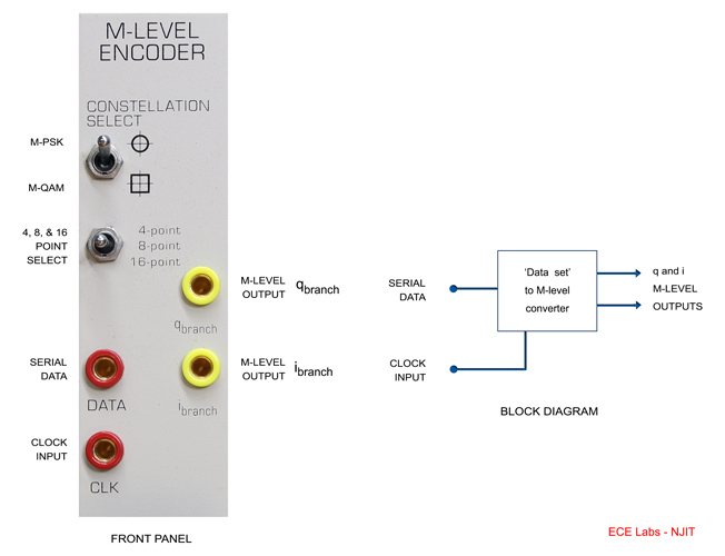
A continuous sequence of TTL-level data bits is grouped into sets of 'L' bits, (where L = 2, 3 or 4). Each set of 'L' bits is encoded to form a pair of M-level baseband signals, q & i .
This q & i signal pair can be represented as 2L unique points (or symbols) in a signal-state-space diagram, or constellation.
Six different encoding formats are available, selected via front panel switches, for generating 4-QAM, 8-QAM, 16-QAM, 4-PSK, 8-PSK & 16-PSK signals.
A 'demonstration' mode for viewing constellation displays is also provided.
USE
OPERATING MODES
Two operating modes are provided, NORMal and DEMO. The PCB mounted jumper, J3 is used to set the operating mode.
NORMal mode provides full functional operation of the module. Both DATA and CLK input signals are required for normal operation.
DEMO mode has limited functional application. It is used only for self test and illustration purposes, to allow the quick setting-up of a constellation display on an oscilloscope. Only a clock signal at the CLK input is required: the DATA input is unused.
INPUT SIGNALS
Two TTL level input signals are required for normal operation: DATA and CLK. The DATA input signal must be synchronised and in-phase with the CLK signal.
CONSTELLATION SELECT
Two front panel CONSTELLATION SELECT switches are used to choose the encoding format required. The upper, 2
position switch selects between either a circular (phase) or square
(amplitude) array. The lower, 3 position
switch selects the number of points in the constellation: 4, 8 or 16.
The following table lists switch settings required for generating the six available constellations.
| Front Panel Switches | Constellation Selected |
|
| Upper | Lower | |
 |
4-point | 4-PSK |
| 8-point | 8-PSK | |
| 16-point | 16-PSK | |
| Front Panel Switches | Constellation Selected |
|
| Upper | Lower | |
 |
4-point | 4-QAM |
| 8-point | 8-QAM | |
| 16-point | 16-QAM | |
The Space Diagrams for the above constellations are shown below,
OUTPUT SIGNALS
Two multi-level analog signals are output, labeled qbranch and ibranch. The number of discrete M-levels and the voltage difference between each level is determined by the front panel CONSTELLATION SELECT switch settings. See the table below.
| Front Panel Switches | Number of M-levels at i & q |
|
| Upper | Lower | |
 |
4-point | 3 |
| 8-point | 4 | |
| 16-point | 8 | |
| Front Panel Switches | Constellation Selected |
|
| Upper | Lower | |
 |
4-point | 2 |
| 8-point | 4 | |
| 16-point | 4 | |
For each of the six available settings, the peak-to-peak amplitude of the qbranch and ibranch signals will always be ±2.5V.
BASIC SPECIFICATIONS
DATA Input serial, TTL-level
CLK Input up to 10kHz, TTL-level
OPERATING MODES PCB jumper selectable
NORM converts sets of input DATA into pairs of multi-level signals
DEMO for testing and displaying constellations only
CONSTELLATION SELECT front panel switch selectable, offering either circular or rectangular, 4, 8 and 16 point constellations
ibranch & qbranch Outputs 2, 3, 4 or 8 level, depending upon constellation selected, ± 2.5V pk-pk
TECHNICAL DETAILS
The signal-state-space diagrams for the six available constellations follow. Note that the data bits representing each symbol are arranged in a Grey Code sequence.
When viewing the above constellations on an oscilloscope, it is important to note that the horizontal axis in the above diagrams is i and the vertical axis is q.
HINT: To assist in determining the correct orientation of the viewed constellation, presenting a logical high to the DATA input of the M-LEVEL ENCODER module (e.g. press the RESET push button on the SEQUENCE GENERATOR module), will only display the 11, 111 or 1111 symbol, depending upon the constellation selected.
QUICK OPERATION GUIDE
- DEMO Mode
- Set PCB mounted jumper, J3, to DEMO position.
- Connect a TTL clock to the CLK input. For example use the 8.3kHz from the MASTER SIGNALS module.
- Select the constellation required via the front panel switches.
- View the qbranch and ibranch output signals on an oscilloscope, in XY mode.
- NORMal Mode with SEQUENCE GENERATOR module
- Set PCB mounted jumper, J3, to NORM position.
- Plug the SEQUENCE GENERATOR and M-LEVEL ENCODER modules into the TIMS rack.
- Connect a TTL clock to both modules' CLK input. For example use the 8.3kHz from the MASTER SIGNALS module.
- Patch the SEQUENCE GENERATOR module's TTL level X output to the M-LEVEL ENCODER module's DATA input.
- Select the constellation required via the front panel switches.
- View the qbranch and ibranch output signals on an oscilloscope, in XY mode.
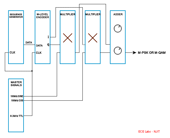
- M-QAM & M-PSK Generation
- Follow steps 1 to 6, as described in section B above, and then patch together two MULTIPLIER and an ADDER module as illustrated below.


