Experiment 1: Three Phase Power Measurements
Objectives
- To demonstrate the line and phase relations in 3-phase balanced networks.
- To study and demonstrate the two wattmeter method of measuring the power in 3-phase networks.
Equipment
- Two digital multi-meters from the stockroom.
- One Set of banana cables and power quality meter Fluke 43B from the stockroom.
- HMRL-3 Resistor Load Cart.
- One three-phase variac.
- One small black box wattmeter (Murata AC power Meter)
- One switch box from cabinet or simple phase circuit breaker.
References
- Richard Dorf, Introduction to Electric Circuits, Ch. 11, 9th edition, John Wiley & Sons, Inc., 2013.
- D. Johnson, J. Johnson, J. Hilburn, Electric Circuit Analysis, Ch. 9, 10, 3rd edition, Prentice Hall, N. J., 1997.
- Turan Gönen, Electrical Machines with MATLAB, pp. 17-41, 2nd Edition, CRC Press, Boca Raton, Fla, 2012.
Background
Three-phase balanced networks are used in the power industry for reasons of economy and performance. Three-phase generators and motors run smoothly, with no torque pulsations, unlike single phase machines. In addition balanced three phase systems may be operated as three wire or four wire systems, with much less copper needed for the power delivered as compared with three single phase systems.
At a power generating plant, the windings of a three phase machine are arranged to provide three voltages, each 120° apart in time and, in the common balanced system, usually all of the same magnitude. These three voltage sources may be connected in a wye (Y) or a delta (∆) configuration. Three phase loads may also be connected in wye or delta connections. The wye connection has a central node to which a neutral wire may be joined, but the delta connection is a three wire system without a node for a neutral or ground) connection.
To measure power in a 3-phase system, it would seem necessary to use three wattmeters, each connected to neutral for a common terminal, and each responding to a line-to-neutral voltage and a line current. One would then add up the powers indicated on each wattmeter. Analysis of such a circuit shows that one wattmeter is redundant, hence the two-wattmeter method of measuring 3-phase power was developed for three wire systems. This method is satisfactory even if the loads are unbalanced. It is necessary to connect the wattmeters taking into account the polarity of their coils. When the current enters the marked terminal of the current coil and the voltage positive is connected to the marked terminal of the voltage coil, the reading represents power absorbed. In that case the algebraic sum of the wattmeters determines the total load power. In reactive circuits it may be necessary to reverse the current coil of one wattmeter in order to get an upscale deflection. This reading is taken as negative when the total power is determined algebraically.
If a 3-phase system has four wires, it is necessary to use three wattmeters, unless it is known that the system is balanced and therefore no current is flowing in the neutral wire. For any balanced N wire system it is necessary to use N − 1 wattmeters to measure the total power.
Prelab
- Assume a phase voltage of 120 V (a line voltage of 208V) in Figure 1.1 and that the
three resistors have values of 800 Ω. Calculate the expected values
of I1 = I2 = I3 for the completely balanced circuit.
- Review the two power meter method for measuring three phase power. Determine how
to connect the meters into the circuits of figures 1.1 and 1.2 to measure power
supplied by the variac. The power meters we use will also read out the voltage and currents
they are measuring but you will need to connect DMVs to measure the remaining phase
voltage and line current as well as to measure the additional voltages and currents
asked for in the lab description. (Line voltages: VAB, VBC, VCA. Phase Voltages: VAN, VBN, VCN. Powers: W1, W2. Line currents: I1, I2, I3. Phase Currents: IP1, IP2, IP3. Neutral current: IN) Print out these circuits and indicate on them where
your watt meters and DVMs will connect.
- Under what conditions will one of the watt meters in a two-wattmeter measurement
read negative powers with a balanced source feeding a balanced load?
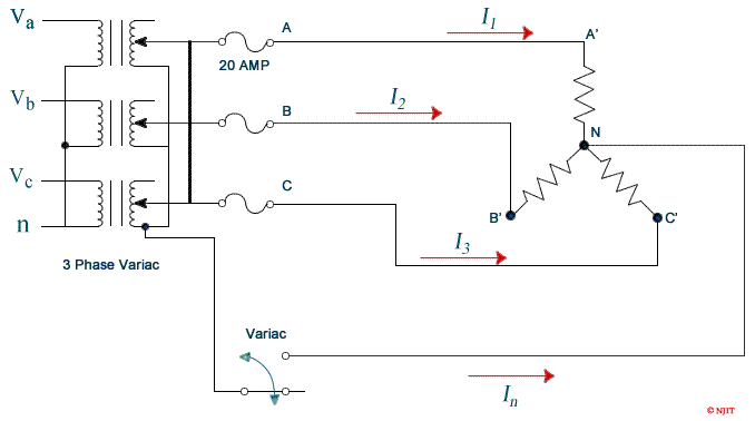
Figure 1.1: The balanced three phase wye connection.
Power Measurements on 3- φ Systems
- Set Load Rack switches so that all 3 resistances are nominally identical. Measure the resistor values before the experiment; their values should be closely matched.
- Connect the three-phase wye circuit as shown in figure 1.1. Connect in the power
meters and the DVM's to allow measurement of the power flowing into the load, the
line voltages (VAB, VBC,
and VCA), the phase voltages
across the resistors (VAN, etc.),
neutral current (IN) and the line currents.
Note: It is important to monitor the current through power meters to ensure that it doesn't exceed the rated current. Low power can be observed when there are large voltages and large currents if there is a low power factor. Note that all measurements in this experiment are AC. Estimate all instrument readings for a source phase voltage of 120V (line voltage of 208V between phases). Select your meter scales accordingly.
- A voltage distribution panel is located on the side of the bench. Use a voltmeter to verify that the voltage is 208 volts between lines. Connect the three-phase variac to voltage distribution panel.
- Carefully adjust the variac output voltage to a phase voltage of 120V (208V line voltage).
- Without connecting the neutral switch at open position, measure and record all currents, voltages
(line and phase) , and power it with different balanced loads of the resistor load cart. Record the results in table 1.1. Turn down the variac and shut the power off.
Note: Measuring power requires the measurement of Voltage, Current, and the phase between them. The Fluke meter has a current clamp which is an inductive pick up that converts current to voltage for measurement by the instrument. The clamp has two scale settings and it is important to check that the meter is set to the same scale as the current clamp. The small black box meters should have their current “coil” connections in series with the circuit. For most measurements (all in this lab) you will want to short the input current connection to one of the voltage “coil” connections. These meters turn on when the voltage exceeds about 65 Volts. They do not read negative power (power flow from the load towards the source). If the meter shows current and voltage but no power then the direction of current through the device must be reversed. The watt meter reading should then be considered negative.
Both Current and Voltage can be very high while there is still almost no power dissipated in the circuit when they are out of phase (low power factor). Hence it is important to always monitor the voltage, current, and power to ensure that none of them exceeds the ratings of the power meters. - Move switch to closed position to connect an ammeter from the neutral of the resistor circuit to the neutral of the three-phase variac and observe the current flow. The current should be read on the 300 mA (or lower) scale.
- Measure all currents, voltages and power readings at same load settings of resistor load cart from step 5. Record all measurements in table 1.1. Turn down the variac and shut the power off.
- Connect the 3-phase circuit as shown in figure 1.2. Raise the line voltage to 120
Volts (phase voltage of 69.3V). Measure and record all currents, voltages and power readings at the same balanced load settings of resistor load cart from step 5.
Note: There will not be enough ammeters for measuring all the phase currents and phase voltages at the same time. Measure the phase currents first, then reconnect to measure the phase voltages.
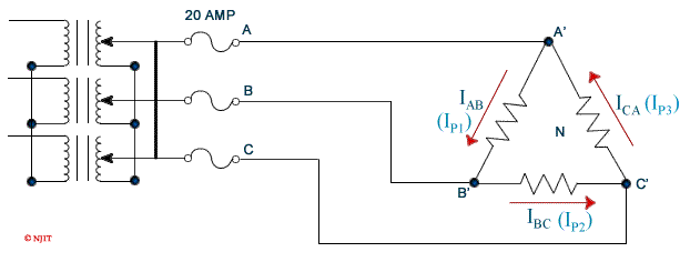
Figure 1.2: The balanced three phase Delta connection.
Report
- Why do we use 208 V for the line voltage on the "wye" circuit but only 120 V for the line voltage on the "delta" load?
- Calculate the total load power in a wye(ү) and delta(Δ) configuration at each balance load from experiment, using the current and voltage data, by two different methods.
- Tabulate the total load power from the calculations from previous question and from the two- wattmeter measurement method. Discuss any differences.
- Verify phase and line voltage/current relationship of wye(ү) and delta(Δ) configuration circuits.
Discussion Questions
- Discuss any differences or similarities for the data obtained for the Y connection with or without neutral connection.
- Would the results be affected if wattmeter 2 were placed to measure the line current B-B’ and both wattmeter potential coils were brought to line C, instead of line B.
- Show a diagram for using only one wattmeter to measure the power in one phase of a balanced three-phase load.
| Table 1.1: Data sheet for Y and Δ connected load. | |||
|
Y w/o neutral |
Y w/ neutral |
Δ connection |
|
Line Voltage Vab
in volts Vbc Vca |
|
|
|
| Phase Voltage VAN in volts VBN VCN Powers W1 in watts W2 |
|
|
— |
| Line/Phase
I1 /Ip1 Currents I2 /Ip2 in amps I3 /Ip3 IN |
— |
|
— |
| Resistor
RA in ohms RB RC |
|
|
|