Lab 4: Load Tests on a Three-Phase Induction Motor and Measurement of the Inrush current
Objectives
- To measure the in-rush current when the motor starts.
- To obtain the load performance characteristics of a three-phase squirrel-cage induction motor.
Equipment
- Two digital multimeters and Fluke Power quality meter with banana cables from the stockroom
- One tachometer from the stockroom.
- One Black Box Power meter
- One resistor load rack. (HMRL Adjustable load cart)
- One Three-Phase Variac.
- One bench mounted Multi-Range DC Power Supply (PSW 250-4.5)
Background
The three-phase induction motor carries a three-phase winding on its stator. The rotor is either a wound type or consists of copper bars short-circuited at each end, in which case it is known as squirrel-cage rotor. The three-phase current drawn by the stator from a three-phase supply produces a magnetic field rotating at synchronous speed in the air-gap. The magnetic field cuts the rotor conductors inducing electromotive forces which circulate currents in them. According to Lenz's Law, the EMFs must oppose the cause which produces them; this implies that the rotor must rotate in the direction of the magnetic field set up by the stator. If the rotor could attain synchronous speed, there would be no induced EMF in it. But on account of losses, the speed is always less than the synchronous speed.
In this experiment the induction motor drives a DC generator. The field of the DC generator is excited separately. Loading the generator by means of a resistor load rack in turn loads the motor. When the motor drives a load, it has to exert more torque. Since torque is proportional to the product of flux and current, with increasing load the relative speed (slip) between the rotor and the rotating magnetic field must also increase.
The three-phase induction motor behaves as a transformer whose secondary winding can rotate. The basic difference is that the load is mechanical. Besides, the reluctance to the magnetic field is greater on account of the presence of the air-gap across which the stator power is transferred to the rotor. The no-load current of the motor is sometimes as high as 30 % to 40 % of the full-load value. The performance of an induction motor may be determined indirectly by loading a DC generator coupled to its shaft as is done in this experiment.
Relevant Equations
- No-load data:
- Load test data:
- Other data:
- Core losses (including friction and windage loss) given by
- The mechanical power output is
- Since one horsepower equals 746 watts, we use the conversion
- Torque is
- Power factor at any load is calculated using
- Efficiency is given by

Prelab
Induction motors are given NEMA codes that indicate a possible range for their inrush current.
| NEMA KVA Code Letters | ||||
| Code KVA/HP Code KVA/HP | ||||
| A | 0-3.14 |
|
L | 9.0-9.99 |
| B | 3.15-3.54 | M | 10.0-11.19 | |
| C | 3.55-3.99 | N | 11.2-12.49 | |
| D | 4.0-4.49 | P | 12.5-13.99 | |
| E | 4.5-4.99 | R | 14.0-15.99 | |
| F | 5.0-5.59 | S | 16.0-17.99 | |
| G | 5.6-6.29 | T | 18.0-19.99 | |
| H | 6.3-7.09 | U | 20.0-22.39 | |
| J | 7.1-7.99 | V | 22.4 & UP | |
| K | 8.0-8.99 | |||
The table gives the ratio of the start-up kVA (total all three phases) to the rated power in HP.
- Considering that our motors are rated at 3 HP and are NEMA Code J, calculate the Inrush current peak on a single phase given a line voltage of 208V (Phase voltage 120).
- Determine how to connect the meters into the circuit of figure 5.1 to measure:
- Total power (W) of the induction motor. Show connections with Analog Power Watt-meters and with Power Quality Meters (Fluke 43B). Hint: Two watt-metter method of measuring power.
- Terminal AC Voltage Vt of the induction motor.
- Line current Ia.
- Generator Voltage Vdc
- Generator Load Current Idc
Part I. Three-Phase Induction Motor - Load tests
- Record the specifications of the Induction Motor (IM)
- Arrange and measure the resistance of the load rack in the same manner as in the previous experiment for 6 different readings. It should range from 500 Ω down to about 30 Ω. Use two banks of the load cart in series since they are rated at 120V. The switch settings on the two banks should be similar.
- Connect the circuit as shown in figure 5.1. and turn the bench panel shunt field rheostat to maximum resistance (CW). Note: Make certain that your power meters can handle the current that you calculated in the prelab. If they can't then you need to short the current coil until after the motor is started. If your power meter has a current clamp and a current rating less than you determined place the clamp around the wire to be measured only after the motor is started.
- Connect the AC power supply from bench panel to the three-phase variac and connect the output of the variac to the circuit.
- Turn on the bench mounted DC power supply and press the set button to adjust the output voltage to 240V and current (IF) to 0.275A by means of its knobs. Adjust the output of the three-phase variac to be 208 V between phases before turning on the motor.
- Press the output button of the DC power supply to connect the 240 volts DC source to the DC motor field shunt to generate the field current IF.
- With no load connected to the resistor load rack, push the start button at the bench panel to run the motor, disconnect the wire shorting the current coil of wattmeter or place the current clamp around the wire to get power readings. If the indicator of the wattmeter is deflected in the wrong direction, simply interchange the connections on the volt side of the meter. Record the terminal AC voltage Vt , the speed, the readings from both wattmeters and the DC load voltage Vdc. in table 5.1 (No load data)
- Connect the resistor loading rack at the generator armature terminals. With each load value, record the reading of Vt, Ia, W1, W2, Vdc the speed N and Idc(10 Amp scale) in table 5.1. (Load test data)
- Shut down the power; disconnect the motor from the power source. Measure the resistance between two of the drive terminals of the induction motor. The stator winding resistor Ra is half the resistance value measured between the power supply terminals of the induction motor marked L1 and L2 on the bench. This is so because in a wye connection two phases are connected in series between terminals L1 and L2.
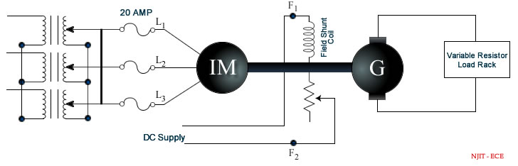
Figure 5.1: Connection for load testing of a three-phase induction motor.
Report
- Show the specifications of the induction motor.
- Complete table 5.2.
- Plot the efficiency η, power factor pf, speed N, horsepower and torque Tm against input current Ia on the same graph sheet.
- Explain the shapes of the pf, rpm and efficiency graphs
Part II. Inrush Current.
In this part you will measure the inrush current of your induction motor. The NEMA code letters on the motor inform the user of the approximate inrush current. Make certain that you write down the NEM A code and the horsepower rating of the machine.
Use the optically coupled usb cable to connect your meter to the computer. Start the Flukeview software on the computer and make certain that it connects with your meter. If not, look at the device manager to determine the port that it is connected to and then choose that port for the Flukeview software.
Use the same circuit wiring as in part I. Choose Inrush current from the meter menu. Enter 1 second for the time of measurement. The parameter labeled maximum current is really the current per division of the display. Set the probe and meter to be able to read the in-rush current calculated in your prelab.
Move the Inrush current menu to start. When you are ready, push start on the meter and then the start button for the motor. The meter won't start measuring until it detects the current flow. The meter should display the current-time curve. Use the Fluxview software to capture this waveform for your report. It is best to capture the data into an excel spread sheet so that you can manipulate the plot for best viewing.
Report
- Show the captured inrush wavefrom.
- Describe any notable features of the inrush current. Can you explain them?
- What is the maximum absolute value of the current during the inrush?
- Determine the estimated inrush current os the induction motor (IM) using its NEMA code.
- For how long does the inrush current persist?
| Table 5.1: Experiment Data | ||||||||
| RL Ohms |
Vt Volts |
Ia Amps |
W1 Watts |
W2 Watts |
P = W1 + W2 Watts |
Idc Amps |
Vdc Volts |
N rpm |
|
|
|
|
|
|||||
| Table 5.2: Calculated Data | |||||
| Ia | pf | N | HP | Tm | η |
|
|
|
|
|
|
Discussion
- Discuss briefly any two methods of starting and industrial induction motor.
- Report on the effect of interchanging any two terminals of the three-phase supply on the rotation.