Understanding reactance in electrical circuits and measurements of the amplitude and phase differences of two signals using a digital oscilloscope.
2. PRELAB
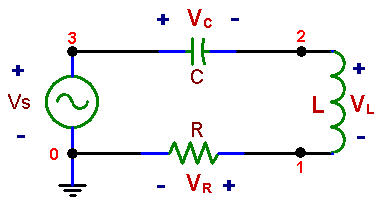
Calculate current and voltage on all components of the circuit shown below for Vs=1V, f = 1 kHz, R = 10 kΩ, C = 10 nF and L = 50 mH.
What are the phase differences between sinusoidal a.c. voltage and current on a resistor, a capacitor, an inductor, and on a power source supplying a circuit consisting of these three components connected in series (as in Fig. 6, below)?
Fig. 6 Series RLC circuit
3. LABORATORY
3.1 Set Frequency
Set the frequency of the generator to about 1 kHz. Particular value of the frequency is not critical, provided that you know what it is. Measure it precisely. Using a DVM, measure voltages across the three circuit elements (R, L, and C) as well as across the voltage source (waveform generator).. Note that you could not do these measurements with an oscilloscope. The voltmeter works here because none of its terminal is grounded. Note also that the relatively low frequency used in this measurement is within the operating range of this instrument.
Do the measured voltage values agree with Kirchoff’s voltage law? Explain!
3.2 Compare Voltages
Compare voltages Vs and VR by using two channels of the digital oscilloscope, with probes attached between points 0 - 1 and 0 - 3. Measure amplitudes and determine the phase difference in degrees. After measurements at about 1 kHz, repeat for another frequency (for example 5 kHz). Note that your measurements determine the phase difference between the source voltage Vs, and current, which is proportional to VR. (Here the bold letters of voltage symbols indicate complex quantities, which give information on both amplitudes and phases)
3.3 Measure Phase
Measure the phase difference between the inductor voltage and current. Use two probes: one for voltage proportional to current (points 0 and 1), the other for voltage across both R and L (points 0 and 2). Using a convenient feature of the digital scope you can now subtract the two signals and view simultaneously the voltage across L and across R, and determine their phase difference.
4. REPORT
Present clearly all results. Compare the results of the amplitude and phase measurements in 1. and 2. with calculations for the frequencies and component values used in the lab.
Does the Kirchoff’s voltage law apply to AC circuits.
Do the results of measurement 3 agree with theory?