LAB 6:
INTRODUCTION TO THE LABORATORY BASIC ELECTRONICS INSTRUMENTS,
THE OSCILLOSCOPE
1. OBJECTIVES
Introduction to the laboratory, familiarity with basic instruments, including analog and digital oscilloscopes.
2. INTRODUCTION
All experiments in the laboratory will be performed at a test bench which has several basic electronic instruments permanently installed. They include: a dc power supply, a waveform generator, a digital voltmeter (DVM), and a digital oscilloscope. A DVM is really a universal meter which can also measure current (both dc and ac) and resistance, with high precision. Other instruments, such as an analog oscilloscope or an analog universal meter, and circuit components (e.g. resistance or capacitance substitution boxes) can be obtained from the stock room, as needed.
An oscilloscope is a basic electronic test instrument which displays images of voltage varying with time. There are two basic types of oscilloscope: analog and digital. An analog oscilloscope displays signals in real time, using amplified input voltage to deflect vertically an electron beam in the Cathode Ray Tube (CRT) while a ramp "time base" signal sweeps it at a predetermined speed horizontally. A digital or digitizing oscilloscope samples the input waveform amplitude and stores the digital information for display on a CRT screen. The analog oscilloscope has been largely replaced today by a digital oscilloscope but professionals still prefer the analog instruments for some applications because it shows an image of a waveform in real time so that you see what is actually coming to the input at a given moment. A great advantage of the digital scope is that digitized waveforms can be stored and viewed independently of the changing input signal, can be easily processed (e.g. added to or subtracted from another signal) or sent to a computer or a printer. It is also easier to measure the period or the amplitude of a signal which is often displayed numerically on the screen. Historically, analog oscilloscope were developed first, and digital oscilloscopes were initially rare and expensive but thanks to a remarkable progress in digital technology their prices declined dramatically. Today, major instrumentation companies, such as Tektronics and HP, make today only digital scopes.
2.1 The Digital Oscilloscope
The purpose of the digital oscilloscope is the same as that of the analog oscilloscope, namely, to display the instantaneous value of input signals versus time on a screen. Whereas the analog scope does this in a straightforward manner by amplifying the input signals and using them to deflect the beam in the vertical direction and using a linear time-base to deflect the beam in the horizontal direction, the digital oscilloscope is based on digital signal processing techniques. The input signal (or signals) is sampled at a rate high enough to be faithfully reconstructed 3*** and the samples are converted into numbers that can be operated on (processed) by a digital computer. This seeming increase in complexity of implementation has the advantage for the user of making it possible to display the result of arithmetic operations, such as sum and difference, on the signals, as well as measuring time difference between points on the signal or the values corresponding to selected points on the signals. This is possible because the data to be displayed on the screen is collected internal to the instrument as an array of numbers indexed by a variable that is related to the x-axis position. Furthermore, data can be transferred to an attached computer via an instrument bus interconnection for plotting, inclusion in a document, or subsequent processing. From an implementation standpoint, it allows the instrument manufacturer to leverage the tremendous advances made in computers and integrated circuits to provide many new and useful features. The influence if the computer on the digital oscilloscope is evident by the extensive use of pull-down menus to access the many functions.
2.2 Digital Oscilloscope specifications
In this section we present and discuss the abridged specifications of a typical, modern, digital oscilloscope such as those found in our laboratories.
Table 2. Abridged specifications for a digital oscilloscope. Characteristics Performance Requirements Vertical System Bandwidth (-3dB) Dc to at least 100 MHz Ac-coupled Bandwidth 10 Hz to at least 100 MHz Range 2 mV/division to 5 V/division Accuracy ±1.9% ***4 Verniers Accuracy about ±3.5% ***5 Single cursor vertical accuracy ±1.2% of full scale ±0.5% of position value Dual cursor vertical accuracy ±0.4% of full scale Rise time 3.5 ns ***6 Dynamic range ±32 V or ±8 division, whichever is less Sweep speeds 5 s/division to 2 ns/division Accuracy ±0.01%±0.2% of full scale ±200 ps Horizontal resolution 100 ps Vernier accuracy ±0.05% Cursor accuracy ±0.01%±0.2% of full scale ±200 ps Display System (8 cm vertical by 10 cm horizontal) Resolution 255 vertical by 500 horizontal points Sampling 8 bit samples, 20 MSamples/sec From the display system specifications we see that there are 32 display points per centimeter in the vertical direction by 50 display points per centimeter in the horizontal direction which is somewhat finer than the size of the spot painted by an analog oscilloscope. The measurement ranges for the digital oscilloscope are comparable to those of a comparable analog oscilloscope. It should be noted that the accuracy of the horizontal system is better than that of the analog oscilloscope because it is based on the accuracy of the clock that controls when the samples are taken rather than on the linearity and accuracy of the sawtooth waveform that sweeps the CRT beam.
2.3 Digital Multimeter
The digital multimeter is a multi-function instrument that can measure ac and dc voltage or current, and resistance. It appears in various incarnations as a laboratory instrument and as a general purpose test instrument out in the field. The instrument used in the laboratory ***7 is based on pre-processing circuitry for each measuring function that converts the input to a dc voltage between ±12 volts. An analog to digital converter produces a digital representation of this dc voltage which is processed by an internal computer to produce an indication for the digital output display. A DC amplifier with a switch selectable gain of 10 or 100 or an attenuator with a gain of 0.1 or 0.01 is used to scale input voltages so that any input range corresponds to 10 volts full scale. This normalized input signal is then sampled and digitized by the analog to digital converter and processed by the computer. Thus, the underlying instrument is a dc voltmeter. Current measurements are achieved by passing the unknown current through a known value of resistance and measuring the resultant voltage developed across this resistance. Resistance measurement is based on passing a known current through the unknown resistor and measuring the resultant voltage drop. High resistance values, where the internal lead resistance is negligible in comparison with the resistance-under-test, are measured using a two-terminal method in which the same two terminals are used to deliver the current to the resistor and to sense the developed voltage. Low resistance values are measured using a four-terminal circuit in which the current to the resistor is supplied via one pair of terminals and the voltage across the resistance is sensed via another pair of terminals that are closer to the resistor. Furthermore, there is negligible current through these voltage sensing leads so that there is no additional voltage drop across the unknown resistor due to the voltage sensing leads.
AC voltage and current is measured by using a true RMS ac-to-dc converter to convert the ac signal to a dc voltage which is measured as before.
Unlike the oscilloscope and many other ac powered instruments which use chassis ground as one of the input terminals, this digital multimeter employs floating measurement(i.e. isolated) circuits and optical coupling to the display unit to permit both inputs of the instrument to be floating.
The following table presents abridged specifications for the digital multimeter.
| Keysight 34401A Digital Multimeter (Formerly Agilent 34401A) | |
|---|---|
| Accuracy | |
| DC Voltage | <±(0.0030% of reading +0.0030% of range) |
| DC Current ***8 | ±(0.005% of reading +0.01% of range) |
| Resistance ***9 | ±(0.002% of reading +0.001% of range) |
| True RMS AC Voltage ***10 | ±(0.04% of reading +0.02% of range) |
| True RMS AC Current ***11 | ±(0.1% of reading +0.04% of range) |
DC Characteristics |
|
| A/D Linearity for Voltage | 0.0002% of reading + 0.0001% of range |
2.4 Analog Multimeter
The underlying instrument in the analog multimeter is a dc microammeter and therefore its fundamental measurement is dc current. DC currents larger than that necessary to achieve full-scale deflection of the basic meter are measured by shunting the meter with a resistor whose resistance is a known fraction of the internal resistance of the meter.
DC voltages are measured by applying them across a known large-valued resistor in series with the microammeter and measuring the resultant current. The current corresponds to voltage (Ohm’s law) which is shown on the appropriate meter scale. The more sensitive the underlying microammeter the larger the series resistance across which the unknown voltage is applied and the smaller the loading effect of the measuring instrument.
Resistance can be measured by using the microammeter to sense the current flow through the unknown resistor due to a known voltage source. Alternatively, the series ohmmeter shown in Fig.1 consists of a known resistance in series with an unknown voltage source. In use, this ohmmeter is “zero-adjusted” by short-circuiting the input and adjusting the shunt across the microammeter to indicate zero ohms at full scale deflection of the meter. When an unknown resistor is placed in series with the known resistor the current in the loop is reduced resulting in a smaller deflection of the meter needle. The scale can be calibrated directly in ohms with zero being at the right hand side (full-scale deflection) and infinite resistance at the left hand side. The ohmmeter is a low accuracy method for measuring resistance but it is quick and simple, and sufficient for many purposes.
AC voltages and currents are measured by using diodes to rectify the ac signals thereby producing pulsating, unidirectional signals whose average value is proportional to the peak value of the ac signal. The meter is calibrated in terms of the rms value of a sine wave.
2.5 DC Power Supply
Constant voltage dc power supplies are common and useful laboratory instruments. Recall that an ideal voltage source is defined as a two terminal element that maintains a prescribed voltage across its terminals regardless of the applied load. In the case of a power supply it is desired that the output voltage be a specified constant over an output current range from zero to several amperes. This is accomplished using electronic voltage regulators to reduce the source impedance to a very small fraction of an ohm ***12
The dual or triple power supplies at each laboratory bench consist of multiple, independent supplies which can be connected in different configurations. These instruments provide two identical, floating ***13 voltage sources with a shared common terminal that can be used to provide positive and negative voltages with respect to the common terminal. The instrument panel has usually switches that allow to operate the two units independently, in parallel (to provide more current) or in series. In the latter case the common terminal of the two units can be used as the common terminal (or ground) of the supplied circuit. In this case three wires have to be run between the power supply and the circuit: positive, negative and common. Such double polarity supply is often required for electronic circuits.
A triple power supply provides an additional independent, floating source.
3. PRELAB
An oscilloscope has an input switch with AC and DC positions. How does this switch modify the oscilloscope input circuit? Can you see an ac signal on the screen is the switch is in DC position? What is the advantage of using this switch?
Consider three instruments: a) digital voltmeter (DVM) at your bench, b) analog voltmeter (AVM), c) an oscilloscopes, and d) waveform generator. You have a rather complex circuit that is connected to a power supply. Can you connect the four instruments between any two points of the circuit to make measurements? Explain.
4. LABORATORY
Equipment needed from the stockroom: an analog universal meter (AVM), the manual for digital oscilloscope at your bench, leads.
4.1 THE INSTRUMENTS AT THE WORK BENCH.
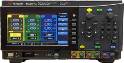
Keysight EDU36311A
Power Supply
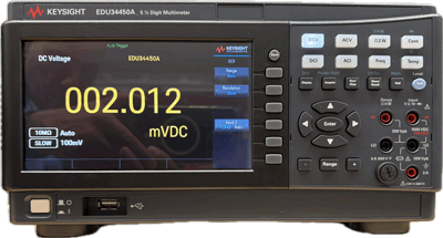
Keysight EDU34450A
Digital Multimeter
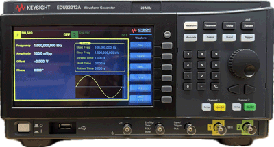
Keysight EDU33212A
Waveform Generator
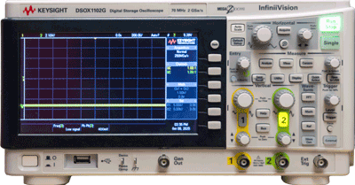
Keysight DSOX1102G
Oscilloscope
-
Familiarize yourself with the instruments at your bench.
Leave the digital scope for later. The dual dc power supply output consists of two independent units which can be connected in different configurations (such as series or dual polarity) or used independently. Check one of these units by connecting a DVM and AVM across its terminals. Turn the voltage adjustment knob to get several different voltage values (for example 1.5V, 14V, 30V. Compare readings on the power supply display with readings on the DVM and the AVM. Note readings of the voltmeters on different ranges of the instruments.
NOTE: A DVM range is set by push buttons and an AVM range by its rotary switch. Make sure also that both instruments are set for DC measurement.
Which voltmeter range should be selected to read best a given voltage? Comment on the precision of voltage measurements on different ranges of the DVM and the AVM and note if its readings agree with the power supply display.
-
Configure the power supply.
Next, configure the power supply for dual polarity voltage, such as +15V and -15V with respect to ground, which is required in many electronic circuits. Using the DVM, measure voltages between the ground (common) and "+", ground and "−" terminal, and also between "+" and "−" terminals.
4.2 THE DIGITAL OSCILLOSCOPE
Important grounding rule:
One terminal of each scope input is connected to earth ground (the outer shield of the BNC coaxial cable). Other instruments (e.g. a waveform generator) or points of a circuit you want to test may also be grounded. Be sure that in such a case you connect the common terminals together. Ignoring this rule may even result in destruction of a tested circuit! Can you see why?
4.2.1 Time Measurements
You will use the waveform generator at your bench to produce a sine wave, a triangle wave, and asquare wave:
- Connect the waveform generator output to one of the channels on the oscilloscope using a BNC cable.
- On the oscilloscope, adjust the Volts/Div control to scale the waveform vertically.
- Adjust the Time/Div control to scale the waveform horizontally.
- Adjust the Trigger Level on the digital oscilloscope until the waveform is stable.
-
Using the digital oscilloscope’s automatic measurement menu, read the period and frequency of the sine wave at:
Low frequency (50–500 Hz)
High frequency (>100 kHz)
- Repeat the measurement using the digital oscilloscope’s cursor measurement system.
How does changing the digital oscilloscope’s trigger level affect waveform stability? How precise are your period measurements using the oscilloscope’s cursors?
HINT: Refresh your memory about rms for different waveforms.
4.2.2 Voltage Measurements Using the Digital Oscilloscope and DVM
Set the waveform generator to produce a sine wave of a few hundred hertz.
- Connect the digital oscilloscope to the waveform generator output
- Connect the digital voltmeter (DVM) to the same terminals
Procedure
- On the digital oscilloscope, use the automatic amplitude measurement to read the peak‑to‑peak voltage.
- On the digital voltmeter (DVM), read the RMS voltage of the same signal.
- Without changing the oscilloscope settings or the waveform generator frequency, repeat the measurements described above for a triangular wave and for a square wave (You change that on the waveform generator).
-
Create a comparison table including:
- Amplitude measured on the digital oscilloscope
- RMS voltage measured on the DVM
- Percent difference between the two readings
Hint
The DVM measures RMS voltage. The digital oscilloscope displays peak‑to‑peak voltage unless you select RMS mode.
4.2.3 AC, DC, and GND Coupling on the Digital Oscilloscope
Procedure
-
On the digital oscilloscope, set the input coupling for Channel 1 to GND.
Use the Vertical Position knob on the digital oscilloscope to center the zero‑volt reference line. -
On the digital oscilloscope, change the input coupling to DC.
On the waveform generator, output a sine or triangle wave.
Observe the waveform on the digital oscilloscope.
On the waveform generator, adjust the DC offset control and observe how the waveform shifts vertically on the digital oscilloscope. -
On the digital oscilloscope, change the input coupling to AC.
On the waveform generator, adjust the DC offset again.
Confirm that the waveform on the digital oscilloscope no longer shifts vertically. -
On the waveform generator, output a square wave.
Observe the square wave on the digital oscilloscope at frequencies above 5 kHz using DC coupling.
Switch the digital oscilloscope to AC coupling and observe the waveform again.
Repeat both observations at approximately 50 Hz.
Questions
- Why does the low‑frequency square wave appear distorted when viewed in AC coupling on the digital oscilloscope?
-
What does the oscilloscope’s input capacitor do at low frequencies?
Make notes of your observations and sketch waveforms seen in tests 2) and 4). Explain what you see.
4.2.4 Frequency Range of the Oscilloscope, DVM, and AVM
Measuring instruments are designed to operate within certain voltage and frequency range and should not be used outside their design specifications. The oscilloscopes in our laboratory are capable of operating at fairly high frequency. The goal for this part will be to determine the useful frequency range of the DVM and AVM.
Procedure
- Connect the oscilloscope, the digital voltmeter (DVM), and the analog voltmeter (AVM) simultaneously to the waveform generator output.
- On the waveform generator, set a sine wave of a few volts amplitude.
-
At low frequency, record the voltage readings from:
- The digital oscilloscope
- The digital voltmeter (DVM)
- The analog voltmeter (AVM)
-
On the waveform generator, increase the frequency by factors of ten.
After each increase, record the readings from all three instruments. - Identify the frequency at which the DVM and AVM readings fall more than 5% below the reading on the digital oscilloscope.
You should notice that readings of voltmeters drop with increasing frequency while the scope indicates almost the same voltage, also the waveform generator output voltage may somewhat vary with frequency too
5. REPORT
Describe briefly the measurement procedure and the results, including sketches of waveforms. Include the table of voltage vs. frequency from part 2.4. Address the topics and answer the questions printed in bold letters in the manual.
In particular discuss these problems:
- Do the scope and DVM measurements agree (to what extend - give % values)?
- What value does a DVM measure for a sine wave? What about a square wave and a triangular wave
- What is the useful frequency range of the DVM and the AVM?
Add any observations or conclusions you wish to make; they enhance your report.
Do not forget to number figures and tables and to give them captions (titles). Number all pages of the report.