Experiment 1: Experiment design-Measurements and Accuracy
Objectives
- To demonstrate the effect of permeability on the inductance of a coil.
- To understand the accuracy of the measuring instruments.
- To measure the accuracy of an analog wattmeter and to determine the effects of voltage, current and power factor on its accuracy.
- To practice designing an experiment
Prelab:
Read the information below. Create the outline of an experiment to demonstrate active power, reactive power, inductance and permeability utilizing equipment in the lab (Appendix 1 shows a list of most of the lab equipment). Be prepared to discuss this experiment with the lab instructor. Make a list of things you can think of that might affect the accuracy of the analog wattmeter
Introduction
Needed equipment and circuit diagrams are not given in this experiment because one of the objectives is that the student design the experiment. This experiment has two goals:
- Design an experiment to demonstrate active power, reactive power, inductance and permeability.
- Understand how an analog wattmeter works and correct the reading it gives. For this lab you are not to use the Fluke meters.
Theory
Some sentences in this section are taken from: http://en.wikipedia.org/wiki/Wattmeter. The traditional analog wattmeter is an electrodynamic instrument (it depends for its function on the electromagnetic forces between a current carrying conductor and a magnetic field). The device consists of a fixed coil, known as the current coil, and a movable coil known as the potential coil.
The current coil is connected in series with the circuit, while the potential coil is connected in parallel. Also, on analog wattmeter, the potential coil carries a needle that moves over a scale to indicate the measurement. A current flowing through the current coil generates an electromagnetic field around the coil. The strength of this field is proportional to the line current and in phase with it. The potential coil has, as a general rule, a high-value resistor connected in series with it to reduce the current that flows through it and to keep the current predominantly in phase with the applied potential.
The result of this arrangement is that on a dc circuit, the deflection of the needle is proportional to both the current and the voltage, thus conforming to the equation W = VA or P = VI. (But not in our meters as the switch uses a current transformer to choose ranges.)
Because the field generated by the potential coil is in phase with the current in the coil and not the potential, there is a slight shift in the angle of the generated field from that of the applied potential. The amount of shift is determined by the series resistance and the inductance of the coil. For power factors close to one this causes little error in the reading. For small power factors the error due to this angle shift can result in large errors in the power reading. Consider a small change in angle, δ between the applied voltage and the current in the potential coil. The relative error in Power reading is given by:
![]() Eq. 1.1
Eq. 1.1
Remembering that cos (θ) is the power factor (pf), we can examine some values of the percent error for differing pfs and δ’s. For a pf of 0.95 the relative error in power reading is only 7% for an error in phase of 10°. However, when the pf is 0.2 a 5° error on the potential coil results in a 43% error in the power read off of the meter. This results from the stationary nature of cos (θ) near θ = 0 and pf = 1 combined with its it’s linearity near θ = 90° when pf=0. You should individually create a 3-d plot or contour plot showing the % error in the meter reading for pf’s ranging from 0.1 to 1 and for errors, δ, from 0°0 to 10°. This should be brought to the second class as your pre-lab for this experiment.
The two circuits of a wattmeter can be damaged by excessive current. The ammeter and voltmeter are both vulnerable to overheating — in case of an overload, their pointers will be driven off scale — but in the wattmeter, either or even both the current and potential circuits can overheat without the pointer approaching the end of the scale. This is because the position of the pointer depends on the power factor, voltage and current. Thus, a circuit with a low power factor will give a low reading on the wattmeter, even when both of its circuits are loaded to the maximum safety limit. Therefore, a wattmeter is rated not only in watts, but also in volts and amperes.
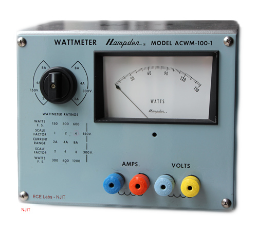
The picture below shows a wattmeter that you may use. At the bottom of the face of the instrument you see the terminals of the current coil and the terminals of the voltage coil. The switch on the left can be set to 150 volt or 300 volt. For each setting there are three ampere settings. Once the voltage and current settings are determined, a scale factor can be read in the table below the switch. This is a factor that you should multiply the actual reading with to get the actual power measured.
In some inductive circuits, the initial current may exceed the fuse rating of the current coil which may result in blowing the fuse up. To prevent this from happening, Make certain to turn the variac all the way down before turning on the power. (Note: this should always be done to protect the Variac)
For the theory of active power (P) and reactive power (Q) and how they are consumed in an inductive circuit, can be reviewed in many books on circuit analysis. The picture below shows an inductor that can be used to design an experiment to illustrate these concepts.
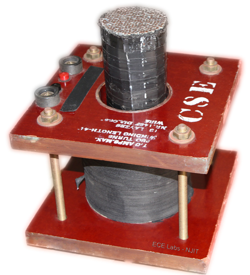
on the inductance and the power factor.
Procedure
Part 1: Inductor Properties with and without core.
- Record the ratings and technical/construction information of your coil. Make certain not to exceed the current rating during this experiment.
- Measure the resistance of the coil with a DMM. How should we measure the resistance of the coil (cold, hot?).
- Arrange to supply the inductor with an AC voltage and measure the Rms current, Rms voltage, power factor (pf), and real and reactive power flow on the meter. Try a few different AC voltages (0 to Max voltage allowed without exceeding the current rating and 10 Volt/Step). Turn off the AC power to the circuit. From your current, voltage and power readings you should be able to calculate the inductance and resistance of the coil under load.
- Measure and record (save the waveform/screenshot) the angle between the voltage and current waveforms at 10 Volt Rms with the oscilloscope. Remember that the oscilloscopes in the lab grounds the probe outer connectors and so no standard oscilloscope probes should have their black-ground connector attached to anything but a ground in your circuit. One useful aid in viewing the current is to attach one of the Fluke-meter current probes to the oscilloscope. These probes convert current to low voltages and the outer conductors can be grounded.
In order to calculate the angle, you should measure the time delay (Δt) between these waveforms. This can be done either by the horizontal menu or measure feature of the oscilloscope.
Turn off the AC power to the circuit - Place an iron core into the center of the coil. Repeat step 4.
- Repeat step 2 and 3 with the iron core into the center of the coil up to the same Max voltage allowed and also 10 Volt/Step.
Part 2: Correction of analog meter-sources of error.
- Set up your circuit to measure the error in the analog wattmeter readings for at least high and low power factor, and for various voltages and currents levels. Your goal will be to determine either a compensation formula or a calibration chart for your meter. You also should get a sense of the accuracy of the measurements it can make.
- Using the Inductor, the iron core and a resistor load rack the power factor of the load can be adjusted. Capacitors are also available to vary the power factor.
- Design a circuit to take measurements with the power meters and explore its accuracy at various levels of power factor (0.1 to 1) with 0.1 step if possible.
- Create an Excel table to enter your measurements. Add the necessary columns in the table to record the load (R), applied voltage (V rms), current (I rms), observed power factor (pf) and calculated VI (apparent power-VA). Record the Power Quality meter reading of P, S & Q and the analog wattmeter reading of P, “correct” power reading and error reading (both absolute (ABS) and relative (REL)). The difference between the Real powers is the absolute error. Add a column to calculate the relative errors.
- Select suitable values of R, C or R/C along with the inductor and take measurements of the power as read from the Fluke Power Quality meter and the analog wattmeter along with voltage, current and pf levels. The lowest power factor can be achieved with no core and no resistor. This should be one of your values of pf examined.
- Using the circuit of step 3, take measurements with the power meters and explore its accuracy keeping the current constant as much as possible while you vary the applied voltage (10 Volts rms/step) and the load (R or R/C combination).
- Create an Excel table and follow instructions of step 4.
- Using the circuit of step 3, take measurements with the power meters and explore its accuracy keeping the applied voltage constant as much as possible while you vary the load (R or R/C combination).
- Create an Excel table and follow instructions of step 4.
- Explore and observe any trends in the errors that you see.
Report
Your report should include the following items: (the first 3 items and the last item should be in every report)
Abstract: A description of the key aspects of the experiment and any results that you found. It is a summary of the key aspects described in the report including any key discoveries or conclusions.
Background: Any theoretical or historical or… background that places the lab in context and explains the observations that you tried to make.
Procedure: The steps you took to make your measurements and any circuit and or phasor diagrams appropriate to help make your report and what you have done clear.
Plot: Make graphs that illustrate the effect of Voltage, Current and Pf on the accuracy of the analog wattmeter readings.
Experimental description for students to explore about active power, reactive power, permeability (magnetic permeability), inductance and resistance of the coil and how that changes when the iron core is inserted. Include your procedure, wiring or circuit diagrams, background and relevant questions for them to answer in their lab reports.
Data: Include here all of the raw data that you took clearly explained and labelled with units and significant figures if appropriate. Include at least one image from the oscilloscope so that you can show how to calculate the angle between the current and voltage.
Analysis: Show how you calculate the inductance of the coil and the value that you get for it. Show how you calculate the pf from the oscilloscope traces. Show your table of relative error for the various power factors. Discuss your error results and derive a formula to correct the wattmeter reading based on the load current, the applied voltage, and the power factor.
Summary: Includes the key accomplishments or tasks and results of the experiment in one or two paragraphs.
Discussion Questions
- How does the resistance under load compare with your measured DMM resistance?
- Discuss additional factors which might affect the accuracy of your meter. What about scale?
- Using your 3-d plot or contour plot from your pre-lab, comment on whether your results on accuracy for different power factors follows one of these contours. Can you determine the angle, d, between the potential applied and the current in the potential coil from your data? How you calculate it?
- Calculate the permeability (magnetic permeability) of the coil you use for your experiment with and without core. Can you determine the material of your core?
Appendix I.
Lab equipment available for use:
- Inductive coils with removable iron cores
- Decade capacitance boxes
- Resistive Load cart
- Fluke Power meters
- Black-box power meters
- Analog power meters
- Transformers
- Current pick-up wands
- Variable resistances
- Oscilloscope
- Oscilloscope Probes
- DMMs