Lab 6: ALUs and the LPM Library
Objectives:
The objective of this experiment is to design and develop code for an ALU that can perform 2’s complement addition and subtraction. Also, we introduce utilizing the LPM library to use components that have been predefined by Altera’s libraries.
Preparation
- Review the design of a ripple-carry adder and how to use the LPM library
Equipment Needed
- Altera DE2 Board
References
- John D. Carpinelli, Computer Systems Organization & Architecture, Addison Wesley, 2001
- Morris Mano, Computer Engineering Hardware Design, Addison Wesley
Background
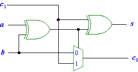
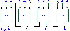
We begin by reviewing the workings of a 4-bit ripple-carry adder. Figure 6.1a below shows the circuit for the full adder. Figure 6.1b shows what the symbol looks like and figure 6.1c shows the truth table. Figure 6.1d displays the 4-bit ripple-carry adder.
 |
 |
|
||||||||||||||||||||||||||||||||||||
| a) Full adder circuit | b) Full Adder Symbol | c) Full adder truth table | ||||||||||||||||||||||||||||||||||||
|---|---|---|---|---|---|---|---|---|---|---|---|---|---|---|---|---|---|---|---|---|---|---|---|---|---|---|---|---|---|---|---|---|---|---|---|---|---|---|
 |
||||||||||||||||||||||||||||||||||||||
| d) Four-bit ripple-carry adder circuit | ||||||||||||||||||||||||||||||||||||||
Figure 6.1: A ripple-carry adder |
||||||||||||||||||||||||||||||||||||||
Part 1
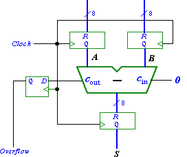
You are to create an 8-bit version of the adder and include it in the circuit shown in Figure 6.2. Your circuit should be designed to support signed numbers in 2’s-complement form, and the overflow output should be set to 1 whenever the sum produced by the adder does not provide the correct signed value.

Include the required input and output ports in your project to implement the adder circuit on the DE2 board. Connect the inputs A and B to switches SW15−8 and SW7−0, respectively. Use KEY0 as an active-low asynchronous reset input, and use KEY1 as a manual clock input. Display the sum outputs of the adder on the red LEDR7−0 lights and display the overflow output on the green LEDG8 light. The hexadecimal values of A and B should be shown on the displays HEX7-6 and HEX5-4, and the hexadecimal value of S should appear on HEX1-0. Use the LPM defined components to create the necessary registers and the D flip-flop.
Part 2
Modify your circuit from Part 1 so that it can perform both addition and subtraction of eight-bit numbers. Use switch SW17 to specify whether addition or subtraction should be performed. Connect the other switches, lights, and displays as described for Part I. If subtraction is performed your circuit should convert the answer to its absolute value form and use LEDG8 to indicate that the solution is negative.
Part 3
Create a circuit using the predefined adder circuit called lpm.add.sub instead of your ripple-carry adder. This circuit will maintain 2’s complement form if an overflow is found on a subtraction.
Prelab Assignment
- Create a block diagram of your 8-bit ripple-carry adder.
- Create algorithm to convert a negative number in 2’s complement to its absolute value form for use in part 2.
Lab Assignment
Develop VHDL code to implement the designs specified in parts 1, 2, and
3 of this experiment.
Be sure to create a separate project for each part and to simulate your circuit
to verify
functionality. For final demonstration, you should be able to show the correct
functionality of
the adder and subtracter specified for each part.