Lab 5: Using VHDL Components
Objectives:
The objective of this experiment is to familiarize yourself with the way to create and instantiate components into your design. This design implementation stresses a structural approach.
Preparation
Review Chapter 2 of Computer Systems Organization & Architecture
Equipment Needed
References
- John D. Carpinelli, Computer Systems Organization & Architecture, Addison Wesley, 2001
- Morris Mano, Computer Engineering Hardware Design, Addison Wesley
Background
This experiment stresses the use of components in the design of VHDL entities. Components are very useful in a structural approach and can be used to model many simple functions such as flip flops, logic gates, counters, etc. They can also be as complex as ALUs and microsequencers.
Part 1
Figure 5.1 shows a 7-segment decoder module that has the three-bit input c2c1c0. This decoder produces seven outputs that are used to display a character on a 7-segment display. Table 5.1 lists the characters that should be displayed for each valuation of c2c1c0.
The seven segments in the display are identified by the indices 0 to 6 shown in the figure. Each segment is illuminated by driving it to the logic value 0. You are to write a VHDL entity that implements logic functions that represent circuits needed to activate each of the seven segments. Use only simple VHDL assignment statements in your code to specify each logic function using a Boolean expression.
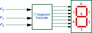
| c2c1c0 | Character |
|---|---|
| 000 001 010 011 100 101 110 111 |
H E L O |
| Table 5.1: Character codes | |
Part 2
Consider the circuit shown in Figure 5.2. It uses a three-bit wide 5-to-1 multiplexer to enable the selection of five characters that are displayed on a 7-segment display. Using the 7-segment decoder from Part 1 this circuit can display any of the characters H, E, L, O, and ‘blank’. The character codes are set according to Table 5.1 by using the switches SW14−0, and a specific character is selected for display by setting the switches SW17−15.
Note that we have used the circuits from part 1 of this experiment and part 2 of experiment 1 as subcircuits in this code. Use five 7-segment displays rather than just one. You will need to use five instances of each of the subcircuits. The purpose of your circuit is to display any word on the five displays that is composed of the characters in Table 1, and be able to rotate this word in a circular fashion across the displays when the switches SW17−15 are toggled. As an example, if the displayed word is HELLO, then your circuit should produce the output patterns illustrated in Table 5.2.
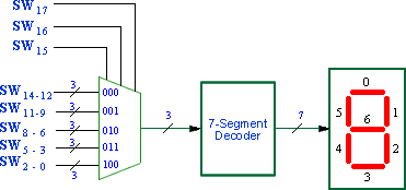
| sw17 sw16 sw15 | Character Pattern |
| 000 001 010 011 100 |
H E L L O E L L O H L L O H E L O H E L O H E L L |
| Table 5.2: Rotating the world HELLO on 5 displays | |
Prelab Assignment
- Review part 2 of lab one to understand how the 5-1 multiplexer was designed.
- Draw a block diagram of your final design for part 2 using components from experiment 1, part 2 and experiment 5, part 1.
Lab Assignment
Develop VHDL code to implement the designs specified in parts 1 and 2 of this experiment. Be sure to create a separate project for each part and to simulate your circuit to verify functionality. For final demonstration, you should be able to decode the characters on a HEX display for part one and rotate those characters on 5 HEX displays for part 2.