ECE 392 - Electrical Engineering Laboratory II
Lab 6: Non Linear Circuits; Positive Feedback
OBJECTIVES
Introduction to non linear circuits and putting positive feedback to good
use.
Comparators, Schmitt trigger, and oscillators.
INTRODUCTION
Most of the circuits studied in this laboratory are linear - output signal is proportional to input signal, or at least should be to a good approximation. Many analog circuits, such as amplifiers and filters, belong to this category. Such circuits are designed to be stable so that a given input results in a unique output. Stability is achieved through negative feedback and positive feedback is deemed undesirable and spells trouble (oscillations). In this series of experiments we explore a different class of circuits which often utilize positive feedback and whose output does not depend uniquely on the input voltage. Digital circuits belong to this class as they sense if signal levels are within certain intervals , defined as 0 or 1, and ignore other values.
A comparator is a circuit which senses input voltage level with respect to some threshold and changes its output state between "low" and "high" which are the circuit saturation voltages, usually equal or close to the supply voltage. A comparator can be easily made from an op-amp but specially designated chips are better for this purpose. A comparator does not need to have the many features required of a good linear amplifier and can trade these qualities for speed of operation. A Schmitt trigger can be thought of as a comparator with hysteresis; it has two thresholds and two output levels. Oscillators do not even need input voltage. They provide their own through a positive feedback circuit and give output waveforms continuously, as long as they are powered.
PRELAB
Using an operational amplifier or a comparator from your parts kit design
a Schmitt trigger with an adjustable threshold and a fixed hysteresis
of your choice between 0.2 V and 0.5 V. Hysteresis is the difference between
input voltages at which output switches states ("low" to "high"
and vice versa) and threshold is their mean value (center of the hysteresis
loop).
Adjustable threshold can be obtained by building a voltage divider
incorporating a potentiometer. A better voltage source for threshold adjustment
may include an op-amp in the voltage follower configuration to buffer
the divider. Use a single polarity power supply. Note: an op-amp output
voltage (in saturation) is defined by the power supply voltage. Comparator
circuits usually require a pull-up resistor between the output pin and
a voltage source which may be different than the chip power supply.
Draw also a schematic of an RC relaxation oscillator obtained by adding an RC network to the Schmitt trigger in the negative feedback loop.
References:
S. Franco "Design
with Operational Amplifiers and Analog Integrated Circuits",
McGraw-Hill 1988. Chapter 8.

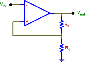
(a) circuit realized with an op-amp

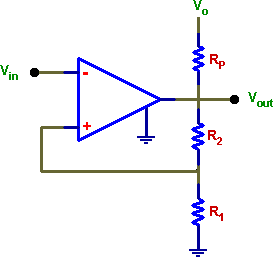
(b) circuit with a comparator and a pull-up resistor Rp.
resistive network R1, R2

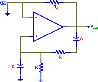
A sign wave oscillator (Wien bridge) with an op-amp. R1 has to be chosen
carefully (it depends on the lamp resistance) for this circuit to work well.
LABORATORY
Equipment needed from the stockroom: scope probe, resistance substitution box, leads.
1. SCHMITT TRIGGER
Assemble and test the Schmitt trigger of your design. Determine hysteresis and the range of threshold voltage. Is hysteresis independent of the threshold setting? If not, how could you improve it (make hysteresis independent of the threshold adjustment)?
2. OSCILLATORS
Assemble one of the oscillators, the RC relaxation circuit or the sine-wave oscillator Wien bridge. Measure frequency of oscillations and check its dependence on circuit components.
Sketch obtained waveforms.
REPORT
Present all schematics and measurements. Describe briefly how the circuits you tested work. Do the measured frequencies and waveform agree with expectations? Include all observations on the circuits performance and if possible give explanations.
What is the role of the lamp in the Wien bridge oscillator?