Experiment 8: Load Test of DC Generator
Objectives
- To obtain the no-load magnetization characteristics.
- To obtain the external characteristics of DC shunt and compound generators.
Equipment
- Three digital multimeters, a set of sheathed banana cables and a power quality meter from the stockroom.
- One tachometer from the stockroom.
- HMRL Adjustable Load Cart.
- A bench mounted Motor-Generator set.
- A bench mounted Multi-Range DC Power Supply (PSW 250-4.5)
- One three phase AC variac.
References
- Vincent Del Toro, Basic Electric Machines, pp. 303-320, Prentice-Hall, 1990.
- A. Fitzgerald, C. Kingsley Jr., and S. Umans, Electric Machinery, Chapter 1, Appendix B, 7th Edition, McGraw-Hill, 2013.
- Turan Gönen, Electrical Machines with MATLAB, pp. 313-316, 2nd Edition, CRC Press, Boca Raton, Fla, 2012.
Background
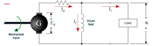
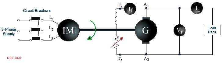
A DC generator, whose schematic is shown in figure 8.1, is an electrical machine which converts the mechanical energy of a prime mover (e.g. DC motor, AC induction motor or a turbine) into direct electrical energy. The generator shown in figure 8.1 is self exciting. It uses the voltage Ea generated by the machine to establish the field current If , which in turn gives rise to the magnetic-field flux Φ. When the armature winding rotates in this magnetic field so as to cut the flux, the voltage Ea is induced in the armature. This voltage is commonly referred to as the armature electromotive force or EMF. The induced EMF is proportional to the rate of cutting the flux and is given by
where
Φ = flux in webers
n = armature speed in rpm
Z = total number of armature conductors
p = number of poles
a = number of parallel paths
The magnetic field necessary for generator action may be provided by (a) permanent magnets, (b) electromagnets receiving their exciting current from an external source, and (c) electromagnets being excited from the current obtained from the generator itself (like that shown in figure 8.1). The use of permanent magnets is confined to very small generators. The electromagnetic excitations listed in (b) and (c) above give rise to generators having somewhat different types of characteristics.
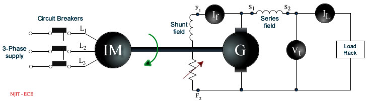
In the case of a compound generator, the series and shunt fields may be connected so as to aid each other, i.e. the fluxes set up by each will add up.
An increase in the total flux will generate a greater EMF. Such a connection is known as cumulative. If, however, the shunt and series winding are so connected that the flux set up by one opposes the other, then the induced EMF will be smaller. This type of connection is called differential.
Magnetization Characteristics
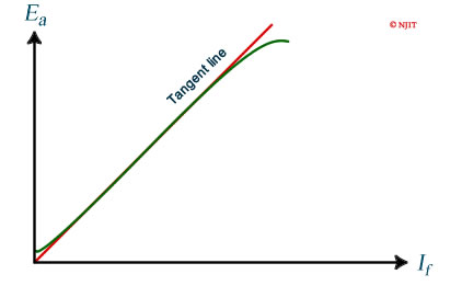
The typical magnetization curve for a shunt DC generator is shown in Figure 8.2 (a). The generated voltage Ea is related to the field winding current If . This generator generates a voltage Ea even in the absence of a current If . The small voltage at zero excitation is due to residual magnetism in the pole material. Thus a self excited shunt generator is self exciting provided that an external voltage of the proper polarity is momentarily applied to the field winding to create the residual magnetic field at the time the generator is put into service for the first time.
The magnetization curve rises very steeply while the magnetic circuit is unsaturated. As the magnetic circuit saturates the curve flattens out. There is a critical field resistance Rc that allows a self excited shunt generator to be self exciting. In order to build up voltage in the generator, the total resistance in the field must be less than the critical resistance.
The critical resistance Rc, for the rated speed of the machine, can be determined from the magnetization curve. To do this, a tangent line is drawn to the magnetization curve starting from the origin. The slope of the tangent line represents the critical field resistance Rc.
Observable Characteristics of a Shunt Generator
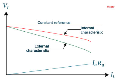
The voltage induced in the armature of a shunt generator is due to the armature wires cutting the magnetic field established by the field current. The induced voltage Ea , and hence the terminal voltage Vt , would be constant if other factors did not affect them. But the armature current Ia affects the terminal voltage Vt in two manners. The armature current distorts the magnetic field thus reducing the terminal voltage Vt. This effect is called armature reaction. In addition to the above there is the ohmic voltage drop Ia Ra, the product of the armature current Ia passing through the armature resistance Ra.
The graph of terminal voltage Vt versus load current IL is called the "External Characteristic" as shown in figure 8.2 (b). It is directly measurable by observing the terminal voltage Vt for different load currents IL. As is obvious from figure 8.1, the load current IL and the armature current Ia differ by the field current If , which can also be measured.
The armature resistance Ra is a measurable quantity. As a consequence the ohmic voltage drop Ia Ra , which is a straight line, can be added to the external characteristic for the calculation of the internal generated EMF of the machine, which is shown plotted as the internal characteristic in figure 8.2 (b). The drop in voltage of the internal characteristic as the load current IL (and hence armature current Ia ) is increased is due to armature reaction.
Magnetization Characteristics
Procedure
- Record the name-plate data of the DC generator.
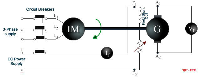
- Connect the circuit as shown in figure 8.3. Note: the coil field and Rheostat that are to be connected to the DC Power Supply are accessible via the bench panel. This is the field shunt winding of the DC generator motor. The large Rheostat on the panel next to the shunt circuit display is hard wired in to the shunt circuitry in series with the field shunt coil. Turn this rheostat to minimum resistance (CCW).
- Connect the AC Power Supply from bench panel to the variac and connect the output of the variac to the circuit.
- Turn on the variac and adjust the output of it to be 208V between phases before running the induction motor (IM)
- Turn on the bench mounted DC Power Supply and press the set button to adjust the output volt to 240 V and current (IF) to 0.000 A by means of its knobs.
- Push the start button at the bench panel to run the generator at rated speed (1730 rpm) and no load.
- Press the output button of the DC Power Supply to connect the 240 volts DC source to the DC motor field shunt to generate the field current If.
- Record the voltage generated (Vt) when If is zero.
- Turn slowly the power supply current knob in clockwise (CW) direction to adjust the field current If (300 mA scale, DC) only in an ascending direction and in 20 mA increments, then record the generated voltage Vt (DC). If the reading goes over the desired value, do not turn the power supply knob back as the DC generator will follow another hysteresis loop pattern, simply record the values of IF and Vt at this point. Repeat until the generated voltage is (almost) at 220 volts. (The rated value is 240 volts.) Note: The maximum field current is about 240 mA.
- After reaching the maximum voltage generated, decrease the field current If in the same manner in 20 mA decrements until 0 mA is reached. At each If , measure and record the voltage Vt. Note: Again, if the reading goes under the desired value, do not turn the power supply current knob back up, just record the values of If and Vt at that point.
- Push the stop button at the bench panel and turn off AC/DC power of the circuit.
Report
- Plot the curves between the generated voltage Va and field current If both for ascending and descending currents.
- Obtain the mean magnetization curve by using the above curve.
- Compute the value of the critical resistance Rc.
- Show the name-plate data of the DC generator.
Characteristics of a Shunt Generator
Procedure
- Complete the circuit as shown in figure 8.4. Turn the bench panel shunt field rheostat to maximum resistance (CW)
- Turn on the three phase variac and press the start button on the bench panel to run the generator at no load and rated speed (1730 rpm). Note: If the measured voltage Vt is only 6 or 7 volts, simply reverse the connection of the induction motor (IM) shunt field winding (L1, L2, L3). The expected voltage generated at no load should be around 220 volts.
- Use two banks of the load cart in series and determine switch settings for at least 8 different
resistances between 150 and 35 Ohms. Each bank is rated at 120 V so the switch settings on the two
banks should be similar.
- Connect the loading rack to the DC shunt generator. Starting with the highest resistance (lowest power dissipation) and decreasing the resistance from there, ensuring that the next step will not exceed the power rating of the load cart, record the field current, If (on 300 mA range, DC), the generated voltage Vt (DC), generator speed N, and the load current IL (on at least a 10A range DC) for the resistance values determined above.
- Push the stop button at the bench panel and turn off the three phase variac.
- Measure the resistance of the armature winding Ra at the end of the experiment by inserting the probes across the DC generator armature connector with all other wires disconnected.
Report
- Plot the external curve of the terminal voltage Vt against load current IL.
- On the same graph draw the voltage drop line Ia Ra against the load current IL .
- Obtain the internal curve using the curves above.
- Graph the internal curve on the same plot as in 1. and 2.
Characteristics of a Compound Generator
Procedure
- Connect the circuit as shown in figure 8.5.
- Turn on the three phase AC variac and push the start button on the bench panel to run the generator at no load and rated speed. Reverse the induction motor shunt field connection if the generated voltage is substantially below the rated voltage of about 210 volts.
- Connect the load rack to the circuit and with the same load resistor value used in characteristic of a shunt generator measure the generator speed N, terminal voltage Vt (DC), load current IL (10 A scale, DC) and field current If (300 mA scale, DC). Follow the same procedure as in shunt generator characteristics, ensuring that you do not exceed the rated power dissipation of the load rack. Be certain to use the higher current scale of the DMM on the bench to measure the load current (IL).
- Stop the bench mounted Motor-DC Generator set and turn off the variac.
- Reverse the series field connection and repeat the previous steps.
Report
From the above data, plot the external characteristics for a compound generator.
Discussion Questions
- Obtain the mean magnetization curve at 125% of rated speed.
- Explain why the total resistance of the field circuit must be less than its critical resistance in a DC shunt generator.
- Explain why an internal characteristic of a shunt generator is not a flat curve.