Experiment 7: Synchronous Motor
(Three-phase Multifunction Machine)
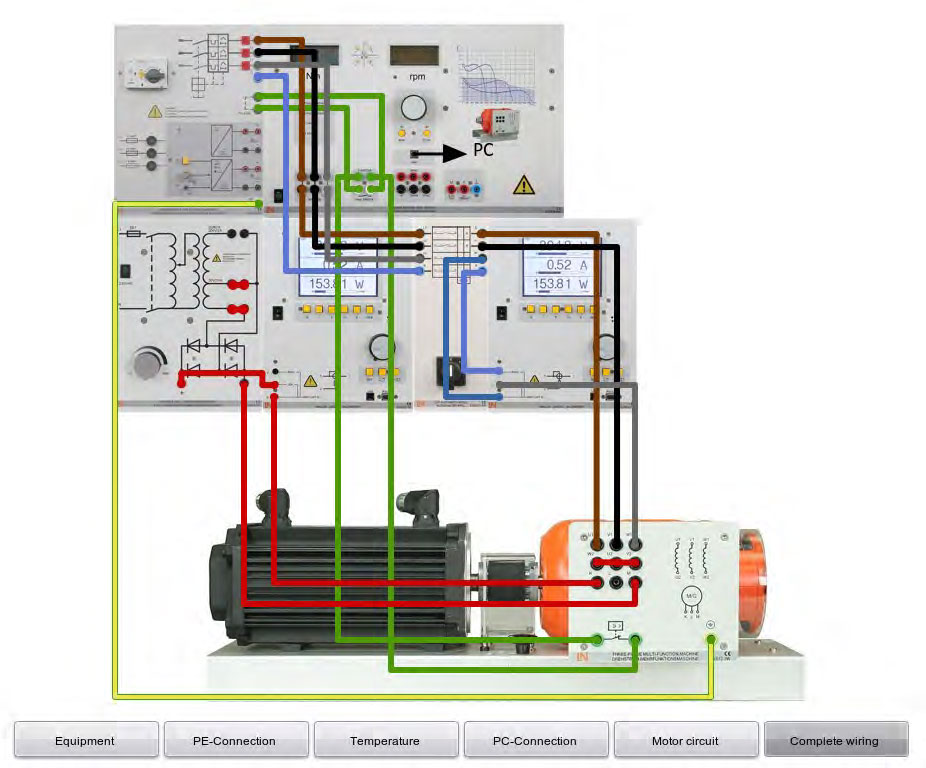
- Set up the circuits according to the circuit and assembly diagrams of Figure 7.1.
- Switch on the servo machine test system and set the "Synchronisation / Speed Control" mode.
More detailed information on the servo machine test system can be found in the corresponding online documentation
Make sure the ammeter/voltmeter are connected correctly
The motor has a very low startup torque. This is not sufficient to start the motor coupled to the servo-machine test system. Therefore, the motor will be accelerated to a speed of 1800 rpm using the servo machine test system.
- Set the exciter voltage to 0 V.
- Press the RUN button at the servo machine test system and set a speed of 1800 rpm
- Connect the motor to the grid via the CO3212-1W switch (switch on).
- Set the exciter current to 1 A as specified in the Table 7.1.
- Press the STOP button at the servo machine test system and change the mode to "Torque control".
- Press the RUN button again and brake the motor using the torque levels for corresponding exciter current as indicated in the Table 7.1.
- Measure the motor current "I" and the speed "n" and enter the measured values into the Table 7.1.
As soon as the motor loses "synchronization", it should be immediately switched off using the cut off switch CO3212-1W, and all measured values for the motor current are to be ignored from this point on. Enter the torque value at which the motor loses "synchronization".
- After the motor loses synchronization repeat the steps 2 - 9 for the next exciting current (2 and 3 A) with corresponding torque levels.
- Switch off the switch CO3212-1W.
- Switch off the servo machine test system.
| Iexc./A | M/Nm | 0.1 | 0.2 | 0.3 | 0.4 | 1.2 |
| 1.0 A | n/rpm | |||||
| I/A | ||||||
| Iexc./A | M/Nm | 0.2 | 0.5 | 0.8 | 1 | 1.2 |
| 2.0 A | n/rpm | |||||
| I/A | ||||||
| Iexc./A | M/Nm | 0.5 | 1 | 1.2 | 1.5 | 2 |
| 3.0 A | n/rpm | |||||
| I/A | ||||||
| Table 7.1: Load Characteristics at Varying Excitation | ||||||
- Repeat steps 2 to 7.
- Press the RUN button again at the servo machine test system.
- Set the servo machine test system to a constant torque level of M = 0.1 Nm as shown in Table 7.7.
- Vary the excitation current using the preset values in the Table 7.2.
- Make sure to measure the power factor cos φ and enter the measured values into the Table 7.2.
- Repeat steps 15 to 17 for constant torque levels 0.5 and 1.0 Nm with excitation current preset values of Table 7.2.
- Switch off the switch CO3212-1W.
- Switch off the servo machine test system.
| M | Iexc./A | 1 | 2 | 3 | 4 | |
| 0.1 Nm | cos φ | |||||
| M | Iexc./A | 1.5 | 2 | 2.5 | 3 | 3.5 |
| 0.5 Nm | cos φ | |||||
| M | Iexc./A | 2 | 2.5 | 3 | 3.5 | 4 |
| 1.0 Nm | cos φ | |||||
| Table 7.2: Phase-shifter Operation | ||||||

- Repeat steps 2 to 7.
- Press the RUN button again at the servo machine test system.
- Set the servo machine test system to a constant torque level of M = 0.2 Nm as shown in Table 7.3.
- Vary the excitation current using the preset values in the Table 7.3 from the highest to the lowest.
- Measure the motor current and enter the measurement results in the Table 7.3. As soon as the motor falls out of synchronization, it is switched off the grid with switch CO3212-1W and all of the measured values taken after this point in time for the motor current are ignored.
- Repeat steps 21 to 25 for torque levels of 0.4, 0.6, 0.8, 1.0, and 1.2 Nm with excitation current preset values of Table 7.3.
- 2Switch off the switch CO3212-1W.
- Switch off the servo machine test system.
| M | Iexc./A | 0.1 | 0.2 | 0.3 | 0.4 | 1.2 | |
| 0.2 Nm | Imot./A | ||||||
| 0.4 Nm | Imot./A | ||||||
| 0.6 Nm | Imot./A | 0.2 | 0.5 | 0.8 | 1 | 1.2 | |
| 0.8 Nm | Imot./A | ||||||
| 1.0 Nm | Imot./A | ||||||
| 1.2 Nm | Imot./A | 0.5 | 1 | 1.2 | 1.5 | 2 | |
| Table 7.3: V-Characteristics | |||||||
Discussion Questions
- Plot the load characteristics at varying excitation (Table 7.1) I = f(M) and n = f (M) in same graph. Explain results. At which break-down torque values for the appropriate exciter currents the motor loses synchonization?
- 8. Plot the phase-shifter operation (Table 7.2) cos φ = f(Iexc). Which type of excitation leads to the generation of inductive or capacitive reactive power?
- 9. List the relationships between grid load and excitation type if you want to use the synchronous motor as a reactive power compensator in the transmission system.
- 10.Plot synchronous motor V-characteristics (Table 7.3) Imot = f(Iexc). At which excitation level does the motor generate capacitive reactive power? How does the synchronous motor respond when the exciter current is lowered to below the stability limit?