Experiment 6: Synchronous Generator
Characteristics and Synchronization
Procedure:
-
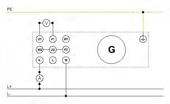
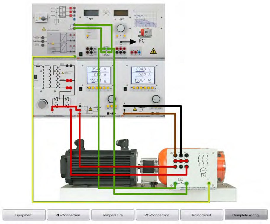
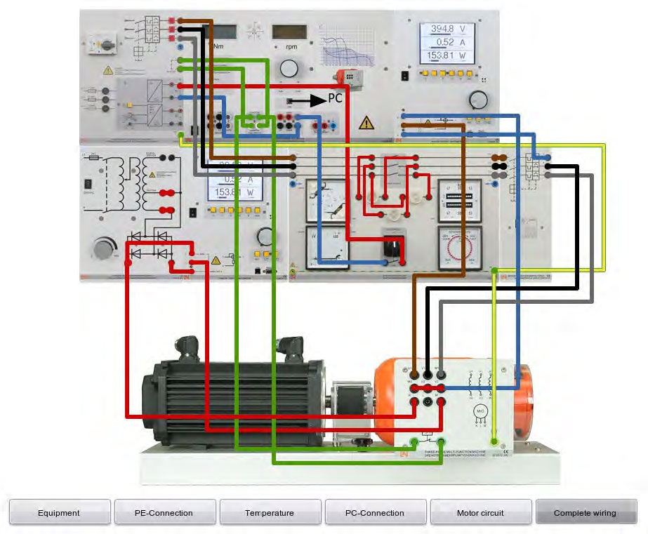
Set up the circuits according to the circuit and assembly diagrams of Figure 6.1.
- Switch on the servo machine test system and set the "Speed Control" mode. Operate the
machine test system as the drive motor for the synchronous generator in a positive
rotation direction.
- Put the machine test system into operation by pressing RUN and set the synchronous
speed of 1800 rpm.
- Set the exciter current as shown in Table 6.1
- Measure the respective generator voltage "V2" for the exciter currents.
- Enter the measured values of "V2" and the torque produced by the drive motor in the Table 6.1.
- Set the exciter current to 3.0 A.
- Follow the speed values from the Table 6.1 and measure the corresponding generator voltage "V2" and the torque produced by the drive motor for each value.
- Record the values in Table 6.1.
- Press the STOP button at the servo machine test system.
| Iexc./A |
0.5 |
1 |
1.5 |
2 |
2.5 |
3 |
3.5 |
4 |
| "V2"/V |
|
|
|
|
|
|
|
|
| M/Nm |
|
|
|
|
|
|
|
|
| |
n/rpm |
500 |
750 |
1000 |
1250 |
1500 |
1800 |
|
| Iexc. =3 A |
"V2"/V |
|
|
|
|
|
|
|
| 1.5Nm |
M/Nm |
|
|
|
|
|
|
|
| |
|
|
|
|
|
|
|
|
| Table 6.1: Synchronous Generator |
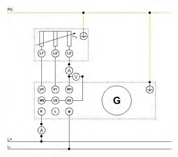
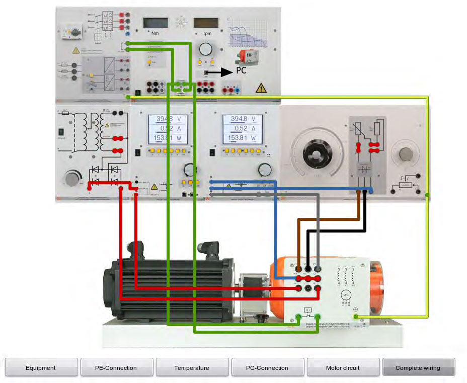
- Assemble the circuits according to the circuit and assembly diagrams of Figure 6.2.
- Switch on the servo machine test system and set the "Speed Control" mode. Operate the
machine test system as the drive motor for the synchronous generator in a positive rotation
direction.
- Put the machine test system into operation by pressing RUN and set the synchronous
speed of 1800 rpm.
- Set the exciter current to 3.0 A.
- Begin with the highest value for the load resistor and each respective value measure and
record the variables of Table 6.2 (Phase values).
- Press the STOP button at the servo machine test system.
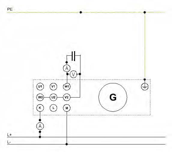
- Modify the circuit as indicated in Figure 6.3.
- Repeat steps 12 to 14,
- For each value of capacitor load measure and record the variables of Table 6.3.
- Press the STOP button at the servo machine test system.
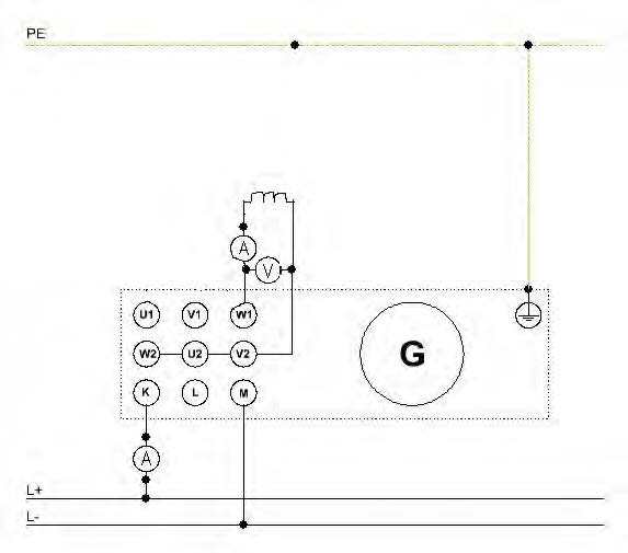
- Modify the circuit as indicated in Figure 6.4.
- Repeat steps 12 to 14,
- For each value of capacitor load measure and record the variables of Table 6.4.
- Press the STOP button at the servo machine test system.
| Iexc. =3 A |
| Ra/Ohm |
I/A |
V/V |
P/W |
| 1000 |
|
|
|
| 500 |
|
|
|
| 300 |
|
|
|
| 200 |
|
|
|
| 100 |
|
|
|
| 50 |
|
|
|
| 30 |
|
|
|
| 20 |
|
|
|
| 10 |
|
|
|
| 5 |
|
|
|
| Table 6.2: Resistor Load Measurements |
| Iexc. =3 A |
| C/µF |
I/A |
V/V |
Q/Var |
| 2 |
|
|
|
| 4 |
|
|
|
| 6 |
|
|
|
| 8 |
|
|
|
| 10 |
|
|
|
| 12 |
|
|
|
| 14 |
|
|
|
| 16 |
|
|
|
| Table 6.3: Capacitor Load Measurements |
| Iexc. =3 A |
| L/H |
I/A |
V/V |
Q/Var |
| 3.20 |
|
|
|
| 1.60 |
|
|
|
| 1.07 |
|
|
|
| 0.80 |
|
|
|
| 0.64 |
|
|
|
| 0.53 |
|
|
|
| 0.46 |
|
|
|
| 0.40 |
|
|
|
| Table 6.4: Inductor Load Measurements |
Grid Synchronization (Three-phase Multifunction Machine)
Procedure
All synchronization methods require the most extreme care and attention!
The generator may under no circumstances be switched asynchronously on line!
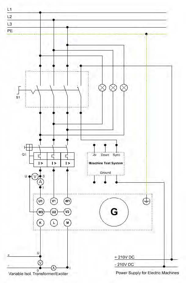
Dark Method
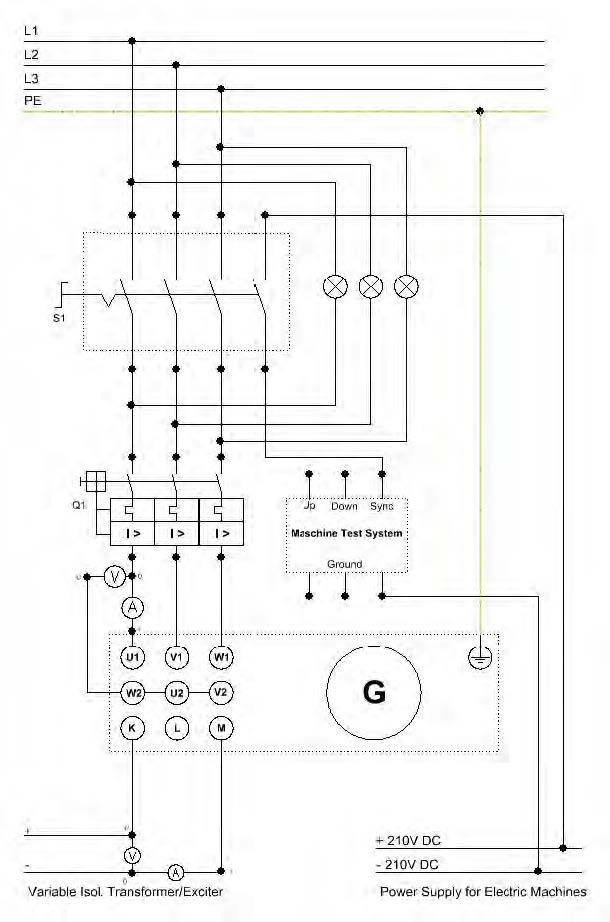
- Set up the circuits according to the circuit and assembly diagrams of Figure 9.
- Switch on the servo machine test system and set the "Synchronization & Speed Control"
mode. Operate the machine test system as the drive motor for the synchronous generator in
a clockwise rotation direction.
- Put the machine test system into operation by pressing RUN and use the control knob to set
the synchronous speed of 1800 rpm (or close to 1800 rpm).
- Switch the exciter unit CO3212-5Q7 on and adjust its current to a V motor close to 120 V.
- Turn on the power supply for electrical machines CO3212-5U7 and motor protection
switch CO3212-1J7.
- If the lamps light up alternately then one phase winding on the generator has to be
exchanged with other. You should switch off the exciter unit, stop the servo brake, switch
off the motor protection switch CO3212-5U7, and do the change of phase windings.
Repeat steps 2 to 5 again.
- Vary the rotation speed using the control knob so that all incandescent lamps light up
simultaneously at low rate.
- At the right moment, i.e. when all of the incandescent lamps are dark, activate the S1
switch consequently connecting the generator on line to the grid.
- This concludes the synchronization. Observe the generator and meters for any abnormality.
- Subsequently disconnect the generator again from the grid opening the power switch S1.
- Switch off the exciter unit and stop the servo brake. Also, turn off the power supply for
electrical machines CO3212-5U7 and motor protection switch CO3212-1J7.
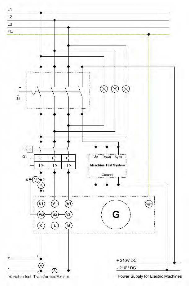
Bright Method
- Modify the circuit connection in accordance with the circuit diagram of Figure 10.
- Repeat steps 2-7 from the "Dark Method" procedure.
- At the right moment, i.e. when all of the incandescent lamps light up the brightest,
activate the S1 switch consequently connecting the generator on line to the grid.
- This concludes the synchronization. Observe the generator and meters for any
abnormality.
- Subsequently disconnect the generator again from the grid opening the power switch S1.
- Switch off the exciter unit and stop the servo brake. Also, turn off the power supply for
electrical machines CO3212-5U7 and motor protection switch CO3212-1J7.
Three-lamp Method
-
Change the circuit connection in accordance with the circuit diagram of Figure 11.
- Repeat steps 2-7 from the "Dark Method" procedure.
- At the right moment, i.e. when the lamp on the left is dark and the other two lamps light up
the brightest, activate the S1 switch consequently connecting the generator on line to the
grid.
- This concludes the synchronization. Observe the generator and meters for any abnormality.
- Subsequently disconnect the generator again from the grid opening the power switch S1.
- Switch off the exciter unit and stop the servo brake. Also, turn off the power supply for
electrical machines CO3212-5U7 and motor protection switch CO3212-1J7.
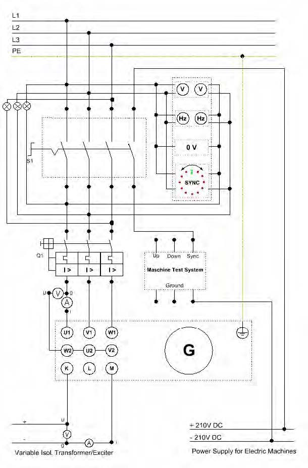
Double Frequency Meter, Double Voltmeter and Synchroscope Method
- Change the circuit connection in accordance with the circuit diagram of Figure 12.
- Switch on the servo machine test system and set the "Synchronization & Speed Control"
mode. Operate the machine test system in a clockwise rotation direction. Turn on the
power supply for electrical machines CO3212-5U7 and protection switch CO3212-1J7.
- Put the machine test system into operation by pressing RUN and use the control knob to
set the synchronous speed of 1800 rpm (or close to 1800 rpm).
- Switch the exciter unit CO3212-5Q7 on and adjust its current until the double voltmeter
indicate the same measured values for both circuits (grid and generator).
- If the lamps light up alternately then one phase winding on the generator has to be
exchanged with other. You should switch off the exciter unit, stop the servo brake, and do
the change of phase windings. Repeat steps 2 to 4 again.
- Vary the rotation speed using the control knob so that the the synchroscope light up
simultaneously at low rate.
- At the right moment, i.e. when the synchroscope comes to a standstill at the mark shown
above, activate the S1 switch consequently connecting the generator on line to the grid.
- This concludes the synchronization. Observe the generator and meters for any
abnormality.
- By activating the S1 switch of the synchronization unit CO3212-6V2 the servo brake is
set to "Torque Control" mode. Increase the drive torque using the control knob in
accordance with the value given in the Table 13.
- Also, vary the exciter current step-by-step as specified in Table 13 below.
- Measure the generator's electrical power output P, the reactive power Q and the power
factor cos φ.
- Enter the measured values into Table 13 included their sign (Pgen = 3 * Pphase;
Qgen = 3 * QPhase).
- Now, set the exciter unit to a constant excitation current of 3.5 A (see Table 14 below).
- Vary the drive torque step-by-step using the control knob, in accordance with the values in
Table 14.
- In the process measure the generator's electrical power output Pphase (Pph) and Pexcitation (Pexc) and enter the values into Table 14 included their sign.
- Based on the rotation speed and the torque compute the mechanical power
Pmech consumed, whereby M corresponds to the torque and ωN corresponds to the nominal
angular frequency.
- Pmech = M · ωN
- ωN = 2 · π · ηsyn / 60
- Based on the variables determined compute the efficiency η of the synchronous generator.
- Please take also into account the power Pexcitation consumed for the excitation of the rotor.
- Finally after successfully completing the measurements disconnect the generator from the
grid opening the power switch S1.
- Switch the exciter unit off and stop the servo brake. Also, turn off the power supply for
electrical machines CO3212-5U7 and motor protection switch CO3212-1J7.
| M = -0.8 Nm |
| Iexc./A |
P/W |
Q/Var |
Cos φ |
| 1 |
|
|
|
| 1.5 |
|
|
|
| 2 |
|
|
|
| 2.5 |
|
|
|
| 3 |
|
|
|
| 3.5 |
|
|
|
| Table 6.5: Generation of Capacitive and Inductive Reactive Power |
| Iexc. = 3.5 A |
|
3*P_gen = |
|
Pexc + P_gen_tot = |
M * ωN = |
(P_elec / P_mech) * 100 = |
| M/Nm |
P_gen/W |
P_gen_tot/W |
Pexc/W |
P_elec/W |
P_mech/W |
η / % |
| -0.4 |
I/A |
|
|
|
|
|
| -0.6 |
|
|
|
|
|
|
| -0.8 |
|
|
|
|
|
|
| -1 |
|
|
|
|
|
|
| -1.2 |
|
|
|
|
|
|
| Table 6.6: Generator Power at Variable Drive Power |
Discussion Questions
- Plot synchronous generator characteristics (Table 6.1) V2 = f(Iexc) and V2 = f(n) separated.
At which exciter current does the synchronous generator achieve nominal voltage? How
does the drive motor's torque respond and why does it respond in this way?
- Plot synchronous generator resistor load characteristics (Table 6.2) V = f(I) and P = f(I) in
same graph. Explain results.
- Plot synchronous generator capacitor load characteristics (Table 6.3) V = f(I) and Q = f(I) in same graph. Explain results.
- Plot synchronous generator inductor load characteristics (Table 6.4) V = f(I) and Q = f(I) in same graph. Explain results.
- Explain the bright, dark and three-lamp synchronization methods.
- What do you need to watch out for with the bright circuit?
- When should two external conductors of the synchronous generator be exchanged?
- What happens if the generator is connected asynchronously on line to the mains?
- cos φ = f(Iexc), P = f(Iexc), and Q = f(Iexc) in same graph. Explain the excitation of the
synchronous generator in terms of the values measured in Table 6.5.
- Plot synchronous generator's power at variable drive power (Table 6.6) P_elec = f(M),
P_mech = f(M), and η/% = f(M) in same graph. Explain results.
- How does the speed of the generator respond when the drive power is increased at variable
drive power (Table 6.6)?