Experiment 5: Torque-Speed Characteristics of Induction Motor
Procedure:
Definition of rotation direction
If you look at the drive shaft end of the machine from the perspective of the working machine (in our case the brake), the rotating direction is positive when it is clockwise. If the motor has two workable shaft ends, then it is the shaft end opposite the cooling vents, collector or slip- rings that is the shaft end which defines the rotation direction.
-
Identify the terminals of the motor.
-
Register the nominal data of the motor in Table 1 using the rating plate.
-
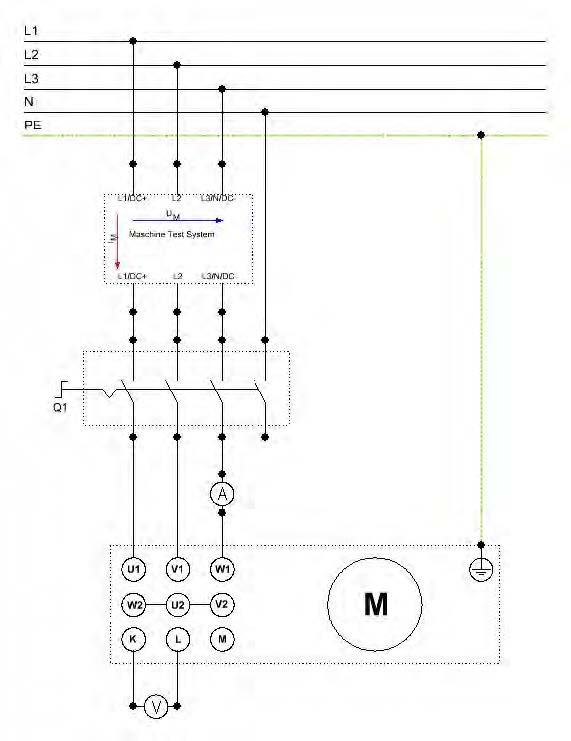
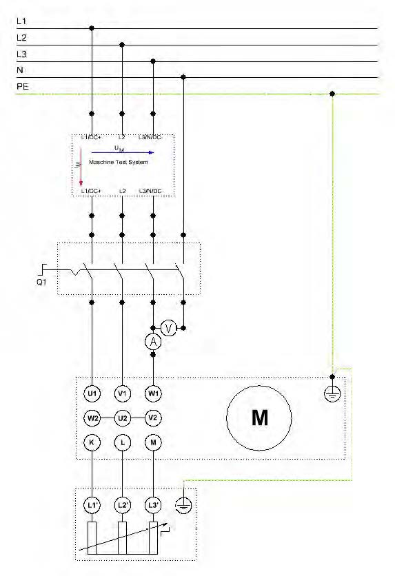
Connect the circuit in accordance with the diagram of Figure 5.1.
-
Then switch on the power supply for the stator winding by setting the cut out switch CO3212-1W in position 1.
-
Measure and record the rotor voltage Vrotor (standstill voltaje) in Table 5.1.
-
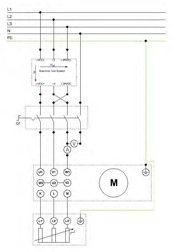
Switch off the motor by setting the cut out switch CO3212-1W in position 0 and modify the circuit in accordance with the circuit diagram of Figure 5.3.
-
Switch on the power supply for the stator winding by setting the cut out switch CO3212-1W in position 1.
-
Identify the motor's rotation direction (CW/CCW) and record in Table 5.1.
-
Set the cut out switch CO3212-1W in position 0 to turn the motor off and modify the circuit in accordance with the circuit diagram of Figure 5.2
-
Switch on the cut out switch CO3212-1W to position 1. Identify the motor's rotation direction (CW/CCW) and record in Table 5.1.
-
Switch off the motor by setting the cut out switch CO3212-1W in position 0.
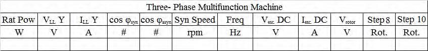 |
| Table 5.1: Nominal Data of the Three-phase Multifunction Machine |
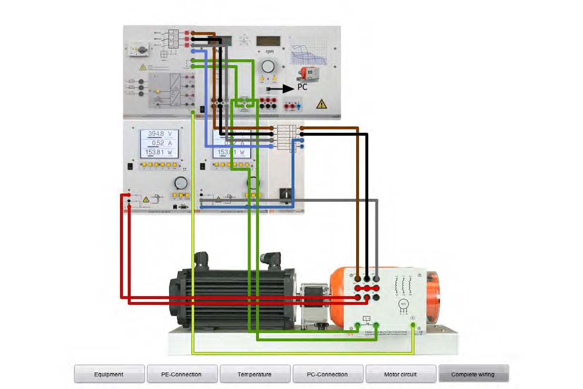
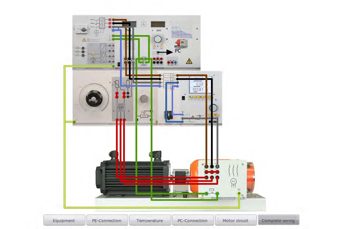
- Set up the circuits in accordance with the circuit and assembly diagrams of Figure 5.3.
- Switch on the servo machine test system as well, this does not subject the motor to any load.
- Adjust the servo machine test system: Mode ""Torque Control"" and starter: 0 Ohm.
- Set the cut out switch CO3212-1W in position 1 putting the motor into operation and observe it.
- Press RUN on the servo machine test system and brake the motor using the torque values specified in the Table 5.2.
- Measure the motor current and speed for each torque setting and enter the measured values into the table 5.2
- Switch off the motor by setting the cut out switch CO3212-1W in position 0.
| M/Nm | 0.2 | 0.4 | 0.6 | 0.8 | 1 | 1.2 | 1.4 |
| n/rpm | |||||||
| I/A | |||||||
| Table 5.2: No-Load Operation | |||||||
- Adjust the servo machine test system: Mode "Torque Control" and starter: 0 Ohm.
- Set the cut out switch CO3212-1W in position 1 putting the motor into operation.
- Adjust a constant torque level to the brake of 1.5 Nm as indicated in Table 5.3.
- Set the starter value Ra = 0 Ohm using the universal load CO3212-6W knob.
- Measure the motor current and speed and enter the measured values into the table 5.3.
- Repeat steps 22 and 23 for Ra values of 2, 5, 10, and 20 Ohms.
- Set the cut out switch CO3212-1W in position 0 to turn the motor off.
| M= | Ra/Ohm | 0 | 2 | 5 | 10 | 20 | |
| 1.5Nm | n/rpm | ||||||
| (Const) | I/A | ||||||
| Table 5.3: Constant Load Operation | |||||||
- tart the "ActiveServo" software. The servo machine test system will turn automatically to "PC Mode".
- The motor is to be braked in 20 steps down to standstill. Adjust the following settings in the software as shown in Table 5.4.
- The respective load characteristics of the asynchronous machine are to be recorded for a total of four starter resistance values (0, 2, 5, 10 Ω).
- Begin with the lowest starter resistance value (Ra = 0 Ohm). All of the load characteristics are recorded in one graph.
- Set the cut out switch CO3212-1W in position 1 to start the motor.
- Click on Start/Stop button or press F5.
- Record the first load characteristic by pressing the symbol or F6 and label the curve with corresponding Ra value.
- Change starter resistance to its next value and record the next load characteristic repeating steps 29 and 30.
- The following parameters are to be recorded: Torque M(n).
- Label and scale the graph as in Table 5.5.
- Save/record the graph created after successfully completing the measurement for your report.
- Save the settings used in the "ActiveServo" software for next steps under the file name "eem5_loadcharacteristic".
- Set the cut out switch CO3212-1W in position 0 to turn the motor off.
| ActiveServo Settings: | |||
| Diagram: Motor characteristics | |||
| Settings | Mode | Speed control |
|
| Presets... | Machine | Synchronous speed [rpm]: 1800 other fields are not required for measuring (motor data can be filled in) |
|
| Circuit | Phase and line variables (3 phase) | ||
| Ranges | Voltage: 350 V Current 25 A |
||
| Slope | Calculate Start: Actual speed End: 0 RPM Steps: 20 Delay after new speed: 200 ms |
||
| Options | don't change default values | ||
| Table 5.4: Software Setting | |||
| Minimum | Maximum | Division | |
| X Axis | |||
| η in rpm | 0 | 1800 | 200 |
| Y Axis | 0 | 3 | 0.2 |
| M /Nm | |||
| Table 5.5: Label and Scale Setting | |||
- Start the "ActiveServo" software. The servo machine test system will turn automatically to "PC Mode".
- Open the file "eem5_loadcharateristic".
- Select the diagram "Load simulation"
- Under the menu "Settings" set the load machine: "Pump / Ventilator".
- Under the menu "View" →"Measured values" mark down all of the mechanical and electrical variables with the exception of the slip.
- The following parameters are to be recorded during this measurement: Torque M(n).
- Set the cut out switch CO3212-1W in position 1 to turn the motor on and adjust the starter to Ra = 0 Ohm.
- Start the measurement and slowly increase the load constant "I" until the power level P2 (mechanical power) shown in the parameter dialog corresponds approximately to 200 W and then save this first "operating point" (F8 or ).
- Without changing the load constant "I" vary the starter value according to the specified values( 0, 2, 5, 10 Ω), waiting a moment each time and then saving the additional operating points (F8 or ).
- Right click on one of the saved working points and select "Show load characteristic".
- Save/record the created graph after successful measurement for your report.
- Save the settings under the filename "eem5_Pump-Ventilator".
- Set the cut out switch CO3212-1W in position 0 to turn the motor off.
- Switch the servo machine test system off.
Discussion Questions
- What causes the rotor standstill voltage?
- What is the correct method to reverse rotation direction?
- Plot the no-load characteristics (Table 2) M = f(n) and I = f(n) in same graph. Explain results.
- Plot constant load operation (Table 3) Ra = f(n) and I = f(n) in same graph. Explain results.
- Plot graph of step 34 of asynchronous motor and explain results in terms of the four load characteristics recorded.
- Plot graph of step 47 of asynchronous motor. How would you describe the characteristic curve of the load torque of the load machine pump/ventilator?